MIC400 Series Camera | Installation and Operation Manual AAAEN | 18
Bosch Security Systems Issue 1
MIC-12PSU Power Supply Unit
The power supply provides power for a single MIC400 non-ir camera unit from a 9v
DC to 29v DC source for installation of the MIC400 camera on vehicle mounted
applications.
Dimensions
Power supply enclosure – 225mm (W) x 70mm (H) x 195mm (D)
This is connected as per the MIC-240PSU as shown previously with the exception
of the following changes:-
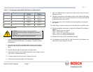
12 or 24 Volt vehicle supply
This should be fed in to connection HD1 nominally marked as mains input,
connections should be as follows:-
Table G – Power Input wiring connections for MIC-12PSU
The rating of fuse FS2 should be changed to a 2A quickblow as opposed to the
rating shown on the PCB.
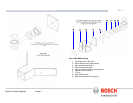
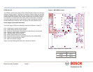
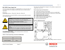
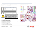
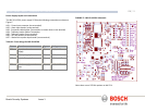
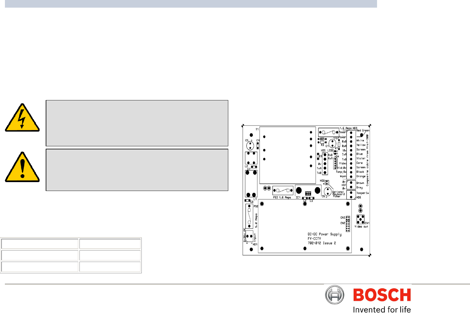
Power Supply Layout and Connections
HD1 – Power Input Connector (screw terminal)
HD2 - Keyboard power connector (demo purposes only, not normally fitted)
HD3 - Composite cable header (Connections to camera head, screw terminal)
HD4 - Telemetry header (Molex Connection)
HD5 - Telemetry header (Screw terminal)
HD6 - Tamper Switch header (Screw terminal)
HD7 – Washer Pump Drive header (Screw terminal)
CN1 - Video out connection header (BNC)
CN2 - Add on card header (plug in)
Figure B – MIC12-PSU Layout
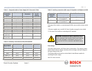
For 12V vehicle installations the composite cable wiring is identical to that shown
earlier in this manual on Table C
Positive HD1-1
Negative HD1-2
Earth and Negative HD1-3
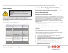
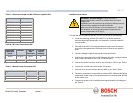
WARNING: Electrical Danger: Ensure all power is disconnected
before opening or working upon any Power Supply Unit.
Installation must be carried out by suitably qualified persons & all
local safety regulations should be followed.
For vehicle mounted installation a specialist installer is
recommended.
CAUTION: It is extremely important to observe the correct polarity,
failure to do so will result in the destruction of the DC-DC power
supply.
CAUTION: This power supply was designed for negative earthed
vehicles only it is not suitable for use with positive earth vehicles.


