2-3
Cisco Video Surveillance 2600 IP Camera User Guide
OL-24127-02
Chapter 2 Getting Started
Installing the Cisco Video Surveillance IP Camera
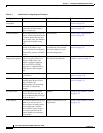
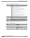
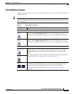
Step 3
Optional. If you are going to connect a speaker and/or a
microphone to the IP camera, attach a Snap-on ferrite
core to the speaker and microphone cables.
A ferrite core must be attached to the speaker or
microphone cable at approximately 10 inches (25 cm)
away from where the cable connects to the IP camera.
When using a speaker and microphone, a single ferrite
core is used for both cables.
Lift the tabs to open the ferrite core, run the speaker and/or
microphone cables through the center of the core, then
snap the core shut to secure it to the cables.
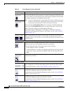
Step 4
Optional. Connect a speaker to the speaker output jack
on the rear of the IP camera.
A speaker plays audio that is captured by a microphone
that is attached to the PC on which you view video from
the camera.
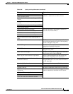
Step 5
Optional. Connect a microphone to the microphone
input jack on the rear of the IP camera.
Connecting an external microphone disables the IP camera
internal microphone. Place the external microphone in a
location that allows it to capture the audio that you want.
The microphone must include a pre-amplifier.
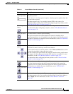
Step 6
Optional. Connect an NTSC or PAL compliant analog
video display device to the video output connector on
the rear of the IP camera.
This device displays video from the IP camera. The
display does not include the time stamp or text that are
configured for the camera.
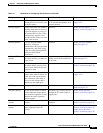
Step 7
Optional. Use the GPIO ports on the rear of the IP
camera to connect external devices that trigger alarms
(connect through alarm input ports) or respond to alarms
(connect through alarm output ports).
You can connect up to two input devices and two output
devices to these ports:
DI1—Alarm input 1
DI2—Alarm input 2
DO1—Alarm output 1
DO2—Alarm output 2
GND—Ground (for use if needed)
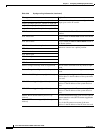
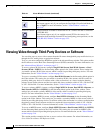
Step 8
Optional. Use the RS485 GPIO ports on the rear of the
IP camera to connect a control device (motorized
housing) that supports the Pelco D protocol.
These ports are labeled D+ (data plus) and D– (data
minus) and accept a cable with two conductors. The cable
fits into the ports in one way. Make sure to insert it
properly.
Step 9
Attach a Snap-on ferrite core to a category 5 or higher
network cable.
A ferrite core must be attached to the network cable at
approximately 10 inches (25 cm) away from where the
cable connects to the IP camera.
Lift the tabs to open the ferrite core, run the cable through
the center of the core, then snap the core shut to secure it
to the cable.
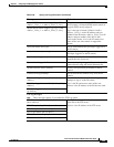
Step 10
Connect a category 5 or higher network cable to the
LAN port on the back of the camera and to a
10/100BaseT hub, router, or switch.
If your network provides PoE, the IP camera powers on.
Skip to
Step 12.
Table 2-1 Installing the IP Camera (continued)
Action Explanation