


1-2
Cisco Video Surveillance 2600 IP Camera User Guide
OL-24127-02
Chapter 1 Overview
IP Camera Overview
• Motion detection—The IP camera can detect motion in up to four designated fields of view by
analyzing changes in pixels and generate an alert if motion is detected.
• Flexible scheduling—You can configure the IP camera to respond to events that occur within a
designated schedule.
• Syslog support—The IP camera can send log data to a Syslog server.
• IP address filter—You can designate IP addresses that can access the IP camera and IP addresses
that cannot access the IP camera.
• User-definable HTTP/ HTTPS port number—Allows you to define the port that is used to
connect to the camera through the Internet.
• DHCP support—The IP camera can automatically obtain its IP addresses in a network in which
DHCP is enabled.
• Network Time Protocol (NTP) support—Allows the IP camera to calibrate its internal clock with
a local or Internet time server.
• Support for C and CS mount lenses—Supports a variety of C and CS mount lenses.
• RS-485/PTZ support—Supports Pelco D protocol, which enables PTZ functions when used with a
supported motorized zoom lens, external pan/tilt mount, and control device.
• Power options—The IP camera model can be powered with 12 volts DC, which is provided through
an optional external power adapter, or through PoE (802.3af), which is provided through a supported
switch.
• Camera access control—You can control access to IP camera configuration windows and live video
by configuring various user types and log in credentials.
• Cisco Media API—The IP camera supports the open, standards based, Cisco Media Application
Programming Interface.
IP Camera Overview
The following sections provide information about the Cisco Video Surveillance IP Camera:
• Physical Details, page 1-2
• DC Auto Iris Lens Connector Pinouts, page 1-6
• Package Contents, page 1-6
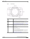
Physical Details
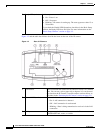
The IP camera includes a reset button, built-in microphone, status LEDs, several ports for connecting
external devices, and two threaded mounting holes, one on the bottom and one on the top.
Figure 1-1 and the table that follows describe the items on the front of the IP camera.