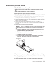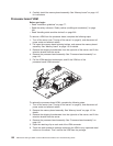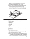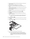
Processor-board
assembly
This
section
contains
instructions
for
removing
the
processor-board
assembly,
the
microprocessor
and
power
module,
and
the
processor-board
VRM.
Note:
When
replacing
the
processor-board
assembly,
you
must
either
update
the
server
with
the
latest
firmware
or
restore
the
pre-existing
firmware
that
the
customer
provides
on
a
CD
image.
See
“Updating
the
firmware”
on
page
39.
Before
you
begin:
v
Read
“Installation
guidelines”
on
page
77.
v
Read
the
safety
notices
at
“Safety
notices
(multilingual
translations)”
on
page
201.
v
Read
“Handling
static-sensitive
devices”
on
page
200.
Complete
the
following
steps
to
replace
a
processor-board
assembly:
1.
Turn
off
the
server
(see
“Turning
off
the
server”
on
page
8),
and
disconnect
all
power
cords
and
external
cables.
2.
Open
the
cover
(see
“Opening
the
cover”
on
page
88).
3.
Pull
open
the
memory-board
retaining
latches,
and
remove
the
memory-board
assembly.
See
“Memory
board”
on
page
115
for
details.
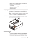
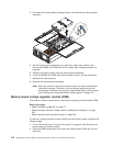
4.
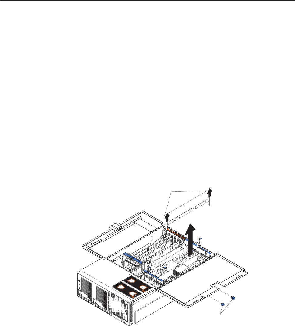
Remove
the
shipping
thumbscrews
from
the
right
side
of
the
server,
and
lift
the
retention
bracket
from
the
server.
N
O
T
E
:
F
O
R
P
R
O
PE
R
A
IR
F
L
O
W, R
E
P
LA
C
E
F
A
NWIT
H
IN
2 M
IN
U
T
E
S
F
RON
T
O
F
B
O
X
N
O
T
E
:
F
O
R
P
R
O
P
E
R
A
IR
FL
O
W, R
E
P
LA
C
E
F
A
N
W
IT
H
IN
2
M
IN
U
T
E
S
F
R
O
N
T
O
F
B
O
X
Lift tabs
Shipping
thumbscrews
Chapter
5.
Field
replaceable
units
119


