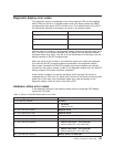
Diagnostic
display
error
codes
The
diagnostic
display
is
composed
of
two
seven-segment
LEDs
on
the
midplane
board.
While
the
server
is
in
standby
power
mode,
the
display
shows
the
CMOS
programmable
logic
device
(CPLD)
revision
level.
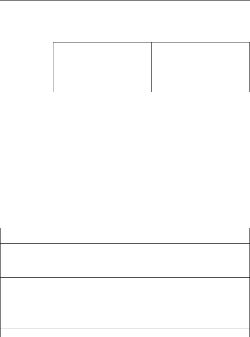
The
revision
levels
of
the
CPLD
are
individually
reported
in
the
display,
as
shown
in
the
following
table.
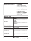
Display
report
Device
P:
An
Processor
board
C:
An
Midplane
board
I:
An
I/O
board
After
the
server
is
turned
on,
the
diagnostic
display
presents
a
two-digit
code
with
a
dot.
If
the
dot
is
at
the
bottom
between
the
two
digits,
then
the
display
indicates
a
Hardware
status
error
code.
If
the
dot
is
at
the
top
between
the
two
digits,
then
the
display
indicates
a
SAL/EFI
progress
code.
When
the
server
is
first
turned
on,
the
hardware
status
error
codes
are
displayed
first,
then
the
SAL/EFI
progress
codes
are
presented
in
the
diagnostic
display.
When
video
is
enabled,
the
SAL/EFI
progress
and
status
indicators
can
also
be
viewed
from
the
system
console.
Codes
on
the
diagnostic
display
track
the
SAL/EFI
startup
progress
until
startup
has
been
completed.
Under
certain
conditions,
the
service
processor
event
log
might
not
contain
a
message
about
a
FRU
fault.
For
these
faults,
the
server
will
usually
not
startup
after
power
on
or
after
reset,
and
a
hardware
status
error
code
will
appear
on
the
diagnostic
display,
which
will
point
to
the
failing
FRU.
Hardware
status
error
codes
If
the
diagnostic
display
on
the
midplane
board
shows
a
single-digit
LED
display,
replace
the
I/O
board.
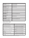
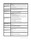
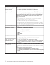
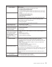
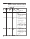
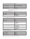
Table
13.
Phase
1
initial
VRM
determination
error
codes
Error
message/explanation
FRU/action
01
(5v
VRM
not
installed)
I/O
board
02
(+5v
PowerGood
Fault)
1.
I/O
board
2.
Midplane
board
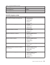
03
(+3.3v
VRM
not
installed)
Midplane
board
04
(+3.3v
PowerGood
Fault)
Midplane
board
05
(+2.5v
VRM
not
installed)
Memory
board
2.5v
VRM
(J32)
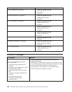
06
(+2.5v
PowerGood
Fault)
Memory
board
2.5v
VRM
(J32)
07
(+2.5v
VRM
not
installed)*
1.
Memory
board
port
1
2.5v
VRM
(J33)
2.
Memory
board
port
2
2.5v
VRM
(J30)
08
(+2.5v
PowerGood
Fault)
1.
Memory
board
port
1
2.5v
VRM
(J33)
2.
Memory
board
port
2
2.5v
VRM
(J30)
09
(+1.8v
VRM
not
installed)
Memory
board
1.8v
VRM
(J31)
Chapter
6.
Symptom-to-FRU
index
181


