Chapter
6.
Symptom-to-FRU
index
This
index
supports
xSeries
450
servers.
Notes:
1.
Check
the
configuration
before
you
replace
a
FRU.
Configuration
problems
can
cause
false
errors
and
symptoms.
2.
For
IBM
devices
not
supported
by
this
index,
refer
to
the
manual
for
that
device.
3.
Always
start
with
“General
checkout”
on
page
33.
The
Symptom-to-FRU
index
lists
symptoms,
errors,
and
the
possible
causes.
The
most
likely
cause
is
listed
first.
Use
this
Symptom-to-FRU
index
to
help
you
decide
which
FRUs
to
have
available
when
servicing
the
server.
The
left-hand
column
of
the
tables
in
this
index
lists
error
codes
or
messages,
and
the
right-hand
column
lists
one
or
more
suggested
actions
or
FRUs
to
replace.
Note:
Some
tables
have
more
than
two
columns;
in
those
instances,
more
than
one
column
on
the
left
is
required
to
describe
the
error
symptom.
Take
the
action
(or
replace
the
FRU)
suggested
first
in
the
list
of
the
right-hand
column,
then
try
the
server
again
to
see
if
the
problem
has
been
corrected
before
taking
further
action.
Note:
Try
reseating
a
suspected
component
or
reconnecting
a
cable
before
replacing
the
component.
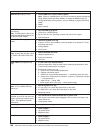
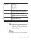
Light
Path
LED
errors
The
system-error
LED
on
the
operator
information
panel
is
lit
when
certain
system
errors
occur.
If
the
system-error
LED
on
your
server
is
lit,
use
the
following
table
to
help
determine
the
cause
of
the
error
and
the
action
you
should
take.
Before
replacing
any
FRU:
1.
Observe
LEDs
on
boards.
2.
View
the
system-error
log.
3.
Run
AMIDiag
program.
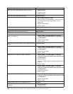
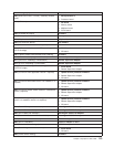
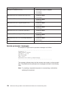
Level
2
Light
Path
LED
FRU/action
None
(An
error
has
occurred
and
cannot
be
isolated,
or
the
ASM
processor
has
failed.)
An
error
has
occurred
that
is
not
represented
by
a
Light
Path
Diagnostics
LED.
Check
the
system-error
log
for
more
information
about
the
error.
All
LEDs
off
(error
log
full)
Note:
″See
Log″
LED
might
be
lit.
1.
System-error
log
is
75%
full;
clear
the
log.
2.
PFA
alert;
check
error
log
for
failure;
clear
PFA
alert;
remove
ac
power
for
at
least
20
seconds,
reconnect,
then
turn
on
server.
3.
Run
diagnostics.
CPU
LED
on
(failed
processor)
Note:
Verify
correct
installation
sequence;
see
“Installing
and
replacing
a
microprocessor
and
power
module”
on
page
100.
1.
See
the
system-error
log.
2.
Microprocessor
1-4.
Note:
To
see
microprocessor
error
LEDs,
remove
the
processor-board
assembly
from
the
chassis,
and
press
the
LED
activation
switch.
3.
Processor
board.
©
Copyright
IBM
Corp.
2003
147


