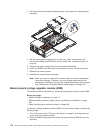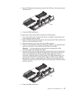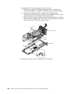
3.
Remove
the
power
supplies.
See
“Removing
and
replacing
a
hot-swap
power
supply”
on
page
90.
4.
Open
the
top
cover
(see
“Opening
the
cover”
on
page
88).
5.
Remove
fans
1
and
2
(see
“Replacing
fan
1
or
2”
on
page
107).
6.
Remove
the
memory-board
assembly.
See
“Memory
board”
on
page
115
for
details.
7.
Remove
the
shipping
thumbscrews
from
the
right
side
of
the
server,
and
lift
the
retention
bracket
from
the
server.
8.
Remove
the
processor-board
assembly.
See
“Processor-board
assembly”
on
page
119
for
details.
9.
If
the
system
contains
a
removable
cable
retainer,
turn
the
thumbscrew
to
remove
it.
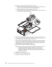
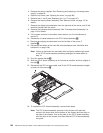
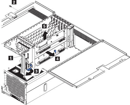
10.
Disconnect
all
cables
attached
to
the
PCI-X
board
assembly1.
11.
Remove
the
shipping
thumbscrews
from
the
left
side
of
the
server,
if
installed2.
12.
Disconnect
the
cables
to
the
hard
disk
drive
backplane
(see
“Hard
disk
drive
backplane”
on
page
138).
Note:
Failure
to
disconnect
the
hard
disk
drive
backplane
cables
might
result
in
the
PCI-X
board
assembly
becoming
entangled
in
these
cables
at
step
14.
13.
Pivot
the
release
handle3.
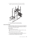
14.
Slide
the
PCI-X
board
assembly
as
far
forward
as
possible,
and
then
slightly
to
the
right4.
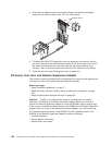
15.
Disconnect
the
PCI
hot-swap
cable,
and
lift
the
PCI-X
board
assembly
straight
up
and
out
of
the
server5.
16.
To
reinstall
the
PCI-X
board
assembly,
reverse
these
steps.
Note:
The
PCI-X
board
assembly
connects
to
the
chassis
with
tabs
that
connect
with
seven
slots
on
the
bottom
of
the
chassis
and
two
slots
on
the
side
of
the
chassis.
Line
up
the
tabs
on
the
PCI-X
board
assembly
with
the
slots
on
the
chassis,
and
then
slide
the
PCI-X
board
assembly
into
place.
124
IBM
xSeries
450
Type
8688:
Hardware
Maintenance
Manual
and
Troubleshooting
Guide


