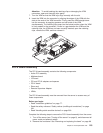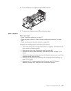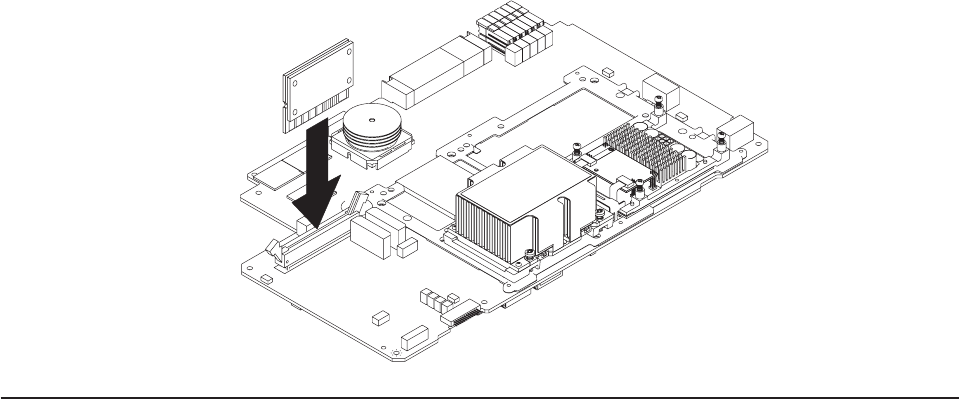
Attention:
To
avoid
breaking
the
retaining
clips
or
damaging
the
VRM
connectors,
open
and
close
the
clips
gently.
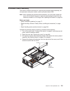
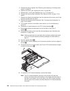
7.
Turn
the
VRM
so
that
the
VRM
keys
align
correctly
with
the
slot.
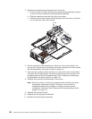
8.
Insert
the
VRM
into
the
connector
by
aligning
the
edges
of
the
VRM
with
the
slots
at
the
ends
of
the
VRM
connector.
Firmly
press
the
VRM
straight
down
into
the
connector
by
applying
pressure
on
both
ends
of
the
VRM
simultaneously.
The
retaining
clips
snap
into
the
locked
position
when
the
VRM
is
firmly
seated
in
the
connector.
If
there
is
a
gap
between
the
VRM
and
the
retaining
clips,
the
VRM
has
not
been
correctly
inserted;
open
the
retaining
clips,
remove
the
VRM,
and
then
reinsert
it.
PCI-X
board
assembly
The
PCI-X
board
assembly
contains
the
following
components:
v
Active
PCI
assembly
v
Midplane
board
v
I/O
board
v
PCI
and
PCI-X
adapters
and
spacers
v
PCI-X
board
v
Riser
card
v
Remote
Supervisor
Adapter
v
VRMs
The
PCI-X
board
assembly
must
be
removed
from
the
server
to
access
many
of
these
components.
Before
you
begin:
v
Read
“Installation
guidelines”
on
page
77.
v
Read
the
safety
notices
at
“Safety
notices
(multilingual
translations)”
on
page
201.
v
Read
“Handling
static-sensitive
devices”
on
page
200.
Complete
the
following
steps
to
remove
the
PCI-X
board
assembly
from
the
server:
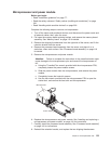
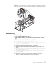
1.
Turn
off
the
server
(see
“Turning
off
the
server”
on
page
8),
and
disconnect
all
power
cords
and
external
cables.
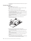
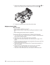
2.
Remove
the
front
bezel.
See
“Removing
and
replacing
the
bezel”
on
page
89.
Chapter
5.
Field
replaceable
units
123


