


21
2. CONTROLS, INDICATORS AND CONNECTORS
20
2. CONTROLS, INDICATORS AND CONNECTORS
6
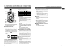
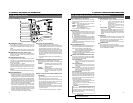
[CH-2 AUDIO IN] CH-2 audio input connector (XLR
3-pin)
Connect the external audio equipment or microphone to
this connector. Set the CH-2 AUDIO IN LINE/MIC select
switch
9
according to the connected equipment.
The audio signal input through this connector is recorded
on the CH-2 audio channel. To record the audio of this
connector, set the CH-2 AUDIO INPUT switch
8
on page
14 to "REAR".
7
Back tally lamp
This lamp lights up when the GY-DV500 enters the record
mode. It blinks during the transition to the record mode.
• Use the VCR Setup Menu item No. 082 BACK TALLY
MODE to select whether or not the lamp should light and
the lighting pattern.
☞ See "BACK TALLY MODE" on page 68.
8
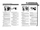
[CH-1 AUDIO IN LINE/MIC] CH-1 AUDIO select
switch
Selects the audio signal input to the
5
CH-1 AUDIO IN
connector.
LINE: Set to this position when connected to audio
equipment, etc. The reference input level is +4 dBs.
MIC : Set to this position when the microphone is
connected. The reference input level is -60 dBs.
MIC +48V ON:
Set to this position when the microphone requiring
+48 V power supply (phantom microphone, etc.) is
connected.
This connector supplies +48 V DC current.
9
[CH-2 AUDIO IN LINE/MIC] CH-2 AUDIO select
switch
Selects the audio signal input to the CH-2 AUDIO IN
connector
6
.
LINE: Set to this position when connected to audio
equipment, etc. The reference input level is +4 dBs.
MIC : Set to this position when the microphone is
connected. The reference input level is -60 dBs.
MIC +48V ON:
Set to this position when a microphone requiring +48
V power supply (phantom microphone, etc.) is
connected. This connector supplies +48 V DC
current.
0
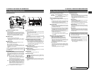
Battery holder
Mount a Flat Shape type battery pack here.
☞ See "Attaching a Flat Shape Type Battery Pack" on page
36.
2-5 Rear Section (Cont'd)
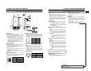
!
Battery holder lock release knob
This knob is used to open the battery case cover. Press the
knob to open the cover.
@
[BRAKER]
The braker trips when the power consumption exceeds the
capacity.
If the braker trips, confirm that the power consumption does
not exceed the wattage rating. Then press BRAKER before
turning the power ON again to put the camera in the
operating status.
If the unit still does not work normally, please consult the
person in charge of professional video equipment at your
nearest JVC-authorized service agent.
CAUTION:
When connecting a component that does not require +48
V power supply, make sure that the switch is not set to this
position before the connection is made.
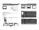
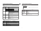
1 4
32
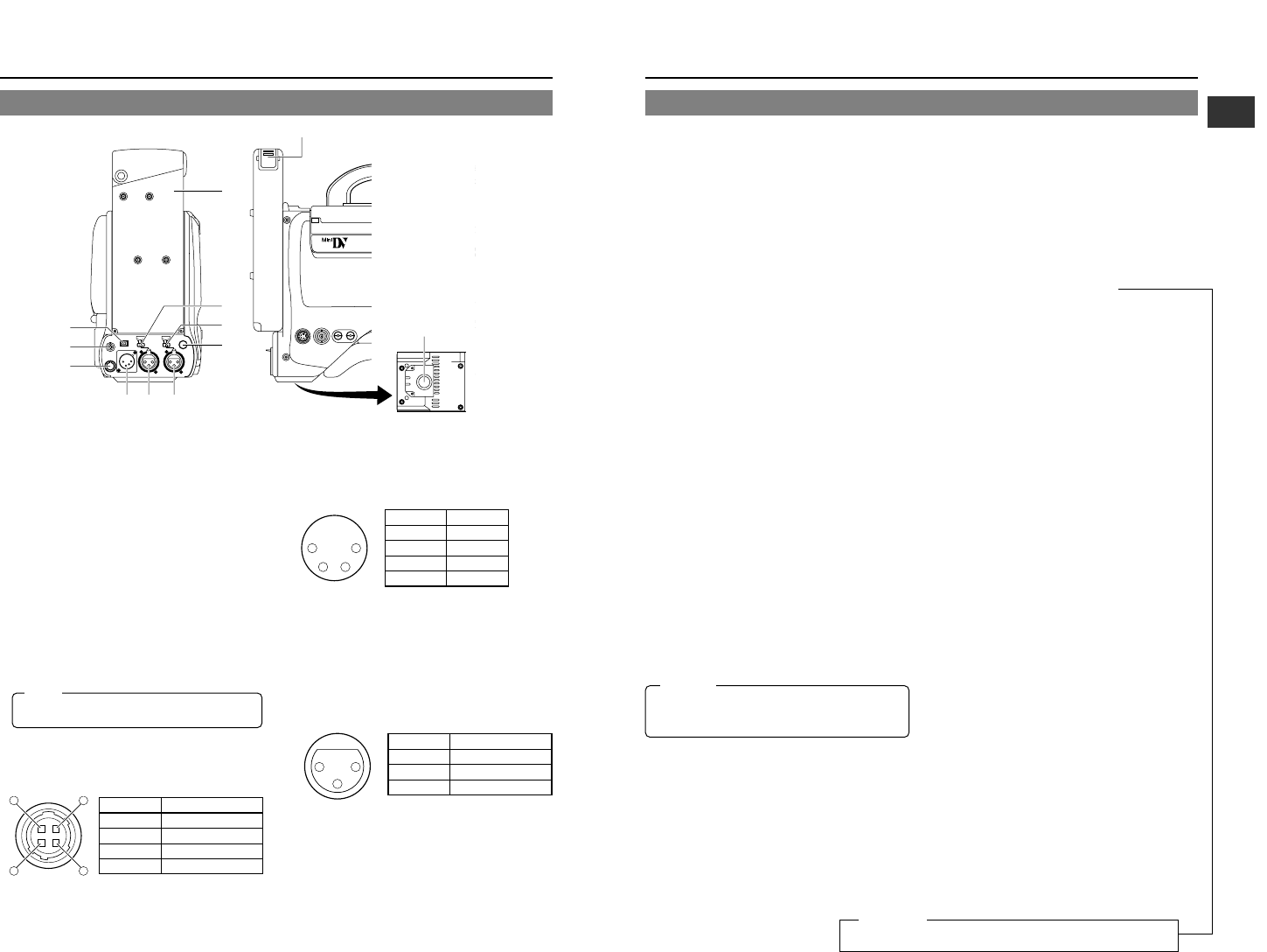
No. Signal
GND
—
—
+12V
1
2
3
4
(Surface profile)
14
23
No. Signal
GND
—
—
DC +12V (power through)
1
2
3
4
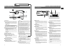
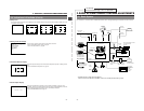
1
[DV] connector
Using a DV cable (optional), a digital video component with
DV connector can be connected here.
This connector is used for input and output of the DV signal
or to input the VCR control signal from the digital video
component with DV connector.
• To record the DV signal from this connector, set the VCR
Setup Menu item No. 126 INPUT SELECT to "IEEE1394".
• To remote control the VCR with a VCR control signal from
this connector, set the VCR Setup Menu item No. 050
REMOTE SELECT to "IEEE1394".
The setup level signal for the DV output connector is not
provided. (NTSC only)
2
[EAR.] earphone jack
This is a stereo mini-jack for connecting an audio monitoring
earphone. Plug in an earphone or headphone with a 3.5
mm diameter plug. (Monaural mini jack)
The earphone can also be used to monitor alarm tones
depending on situations.
The sound from the monitoring loudspeaker is interrupted
when an earphone is connected here.
3
[DC OUTPUT] connector
Power output connector to a wireless microphone
transmitter, etc. The supply voltage is identical to the voltage
supplied to the unit (DC 12V max. 0.1 A).
4
[DC INPUT] connector (XLR 4-pin)
Power input connector for 12 V DC. Connect with the AA-
P250 optional AC power adapter. When a cable is connected
here, the power supply from the battery pack is interrupted
and the source is switched to the power supplied through
this connector.
5
[CH-1 AUDIO IN] CH-1 audio input connector (XLR
3-pin)
Connect the external audio equipment or microphone to
this connector. Set the CH-1 AUDIO IN LINE/MIC select
switch
8
according to the connected equipment.
The audio signal input through this connector is recorded
on the CH-1 audio channel. To record the audio of this
connector, set the CH-1 AUDIO INPUT switch
7
on page
14 to "REAR".
(AUDIO IN connector)
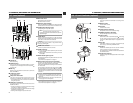
2-5 Rear Section
Bottom
TALLY
DV
AUDIO IN
CH-1
DC INPUT
EARPHONE
DC OUTPUT
LINE MIC
+48V
ON
CH-2
LINE MIC
+48V
ON
VTR
REMOTE
SYNC IN
MIC
LEN
TEST OUTPUT
Y/C OUT MONITOR OUT
LINE OUT
CH-1 CH-2
PUSH
DV CAMCORDER
GY-DV500
BREAKER
q
w
e
rt y
u
o
i
0
!1
B
Memo:
Only the left-channel sound is heard when a stereo mini-
jack is used.
No. Signal
GND
HOT
COLD
1
2
3
2
1
3
For servicing
See the service manual page 1-1 “RESETTING THE POWER CIRCUIT
PROTECTION BREAKER”.
←