


29
2. CONTROLS, INDICATORS AND CONNECTORS
28
2. CONTROLS, INDICATORS AND CONNECTORS
●
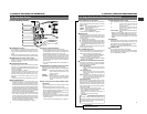
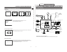
Status 1
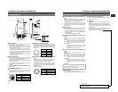
In addition to the information on the Status 0 screen, this screen displays audio indicators and information on remaining tape,
voltage and lens F-number.
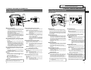
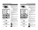
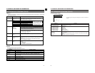
2-9 Indications in Viewfinder (Cont'd)
Indication Indication Contents
SCENE FILE A, B, OFF
WHITE BAL A, B, PRESET, FAW
FILTER 3.2K, 5.6K, 5.6K+ND
SHUTTER OFF, 1/100, 1/250, 1/500, 1/1000, 1/2000, 1/60.1 to 1/2084.6 (in VARIABLE mode),
EEI (in ALC mode)
GAIN -3dB, 0dB, 6dB, 9dB, 12dB, 18dB, LOLUX, ALC
IRIS LEVEL NORMAL, BACK L, SPOT L
FULL AUTO ON, OFF
REC TIME Remaining tape time or time code.
●
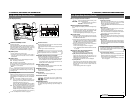
Status 2
This screen displays the camera setup statuses.
Event display is not available while this screen is displayed.
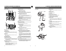
8
(Example)
CH1- - - - + - -
CH2- - - - + - -
9
STBY
SAVE
STOP
REC
FF
REW
EJECT
0
(Example)
< 60
(Example)
12: 34: 56: 20
A
(Example)
12.4V
B
OPEN, F2, F2.8, F4,
F5.6, F8, F11, F16,
CLOSE
C
(Example)
M:99
Shows the input level of the audio input channel.
Display ON/OFF can be selected using the VF DISPLAY menu screen.
☞ See "AUDIO DISPLAY" on page 72.
VCR in standby mode
VCR in save mode
VCR in stop mode
VCR in record mode
VCR in fast-forward mode
VCR in rewind mode
VCR in reverse search mode
Remaining tape indication (displayed in 1-minute steps)
When the tape is used for a long time, the remaining tape may not be
indicated accurately. At the beginning of the tape, in particular, the indication
may show smaller value than the actual one.
Time code display
Time code display is available when the "REC TIME" item on the VF DISPLAY
menu screen is set to TIME CODE.
☞ See "REC TIME" on page 72.
Voltage indication (displayed in 0.1 V steps)
Shows the F-number of the connected lens.
It is not displayed when the lens is removed. For some lenses, no display
appears.
Display ON/OFF can be selected on the VF DISPLAY menu screen.
☞ See "F NO.DISPLAY" on page 72.
In the Super Scene Finder (S.S.F.) mode, the number of memorized scenes
is shown.
M: In MARK mode
C : In CUE mode
Number: Number of memorized scenes
Display position
Function
Display
Note:
When the RS-232C cable
is connected, the VCR
operation mode may not
be displayed correctly.
27
28
2. CONTROLS, INDICATORS AND CONNECTORS
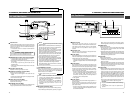
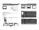
Alarm message display
ACCU -FOCUS
G
F
I
F5.6
STBY 4V21.<60
B
CH1 ----+--
CH2 ----+--
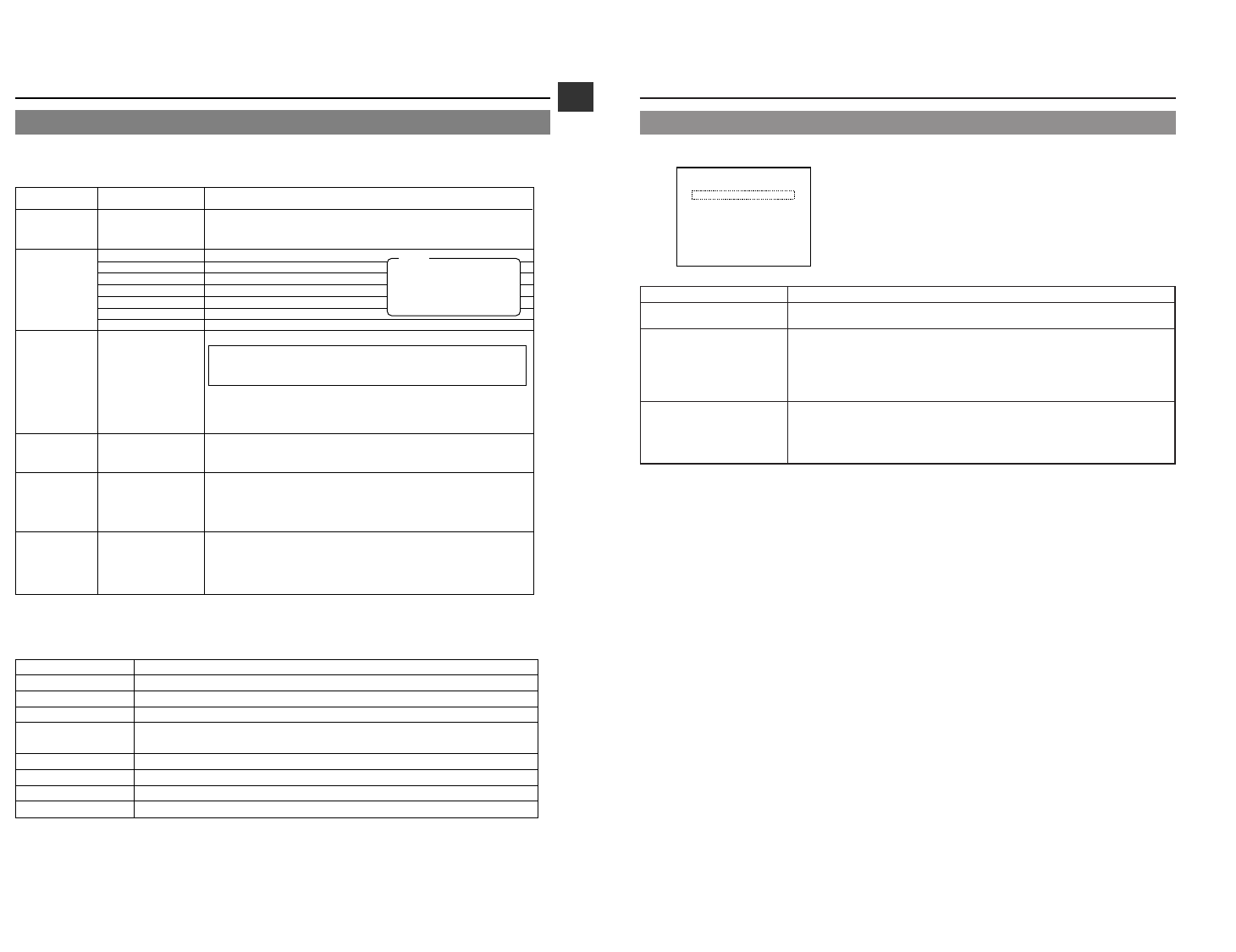
Ⅲ Alarm Message Display
The following alarm messages are displayed on the status 0 and status 1
screens.
Indication Contents
LOW BATTERY The battery capacity is nearly exhausted.
CLOSE CASSETTE COVER The cassette cover is not closed.
VTR WARNING [HEAD] Head clogging
VTR WARNING [SERVO] Servo error
VTR WARNING [DEW] Condensation
VTR WARNING [HARD] Hardware error
VTR WARNING [STOP] Operation stopped
VTR WARNING [REW] Rewinding abnormality
TAPE NEAR END Remaining tape time is less than about 2 minutes in the record mode
TAPE END Tape end reached
REC INHIBIT An unrecordable videocassette (the switch on the back of the cassette is set to SAVE) is
inserted.
NO TAPE VTR trigger is pressed with no tape loaded.
2-9 Indications in Viewfinder (Cont'd)