


91
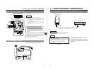
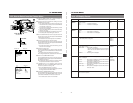
14. OTHERS
• The front section's recording level control cannot be used to change the recording
level of the sound input to CH2. Use the side section's CH2 recording level control
for this purpose.
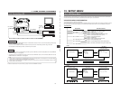
TROUBLES WITHOUT ERROR CODE OUTPUTS
Symptoms
Remedy
Power cannot be switched ON.
• Is power supply connected properly?
• Is battery pack recharged?
• When the lithium battery is depleted, it may not be possible to turn on the power.
• Was the power turned ON immediately after being turned OFF?
Wait at least 5 seconds before turning the power ON again once it has been turned
OFF.
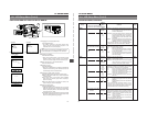
Operation buttons on the GY-DV500 don't
work.
• Is the cassette cover open?
The GY-DV500 remains inoperative as long as the cassette door is open.
Recording is not possible. • Is switch on cassette set to REC? If it is set to SAVE, set it to REC.
• When not connected via the DV connector, is the VCR Setup Menu item No. 126
INPUT SELECT set to “IEEE1394”?
If so, set to “CAMERA”.
Noise interferes with playback video.
• Video head may be clogged with dirt. Clean head with the special head cleaning
tape. (See page 7 and the separate sheet “Precautions for Use of Head Cleaning
Tape”.)
Time code data is not shown as on-
screen-display.
• Time code data is not shown as on-screen-display during recording or playback.
The data is shown only on the counter display.
Time code and user's bit data are not
shown on the counter display.
• Is the COUNTER switch set to "CTL"? If so, set the switch to "TC" or "UB".
Remaining battery power display is
incorrect.
• The VCR Setup Menu item No. 396 BATTERY TYPE may not be set correctly in
accordance with the type of battery in use. If the menu item setting is incorrect, set
it correctly using the VCR setup menu item BATTERY TYPE.
• Is the battery old?
Battery alarm is displayed and the GY-
DV500 enters the non-operating mode
even when a fully charged battery is used.
Cassette cannot be ejected after the
power is turned ON.
• The capacity of the power supply may be insufficient. Check the power voltage.
Viewfinder image looks dark or unclear.
• Adjust the viewfinder's contrast and bright controls.
• Is the filter turret set to 5600K+ND?
• Is the iris closed?
• Is the shutter speed too fast?
• Is the viewfinder cable correctly connected?
Noise appears when playing back a tape
recorded on another unit.
• When a tape recorded on another unit is played back or used for recording, this
phenomenon may occur due to tracking errors.
The transient section between scenes
recorded on other units and those
recorded on this unit may appear
disturbed.
The front section's recording level control
doesn’t work.
• Is the VCR Setup Menu item No. 246 FRONT VOLUME ENABLE set to "DISABLE".
If so, set to "ENABLE".
The front section's recording level control
doesn’t change the recording level of the
sound input to CH2.
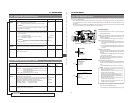
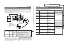
14-1 Troubleshooting (Cont'd)
• Is the SERVO indicator or “SYNC INH” displayed on the counter display?
If so, check the input sync signal.
Recording operation stopped.
Even if the image appears in the
viewfinder, the signal is not output to the
MONITOR OUT or YC OUT connectors.
(U-ver. only)
• When not connected via the DV connector, is the VCR Setup Menu item No. 126
INPUT SELECT set to “IEEE1394”?
If so, set to “CAMERA”.
Sound and picture are disturbed during
playback.
• Is the sync signal input to the SYNC IN connector disturbed? If so, check and
remedy the input sync signal.
For servicing
See the service manual page 2-7 “2.4.3 Cleaning”.
→
92
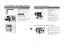
14. OTHERS
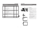
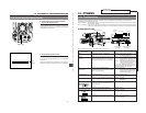
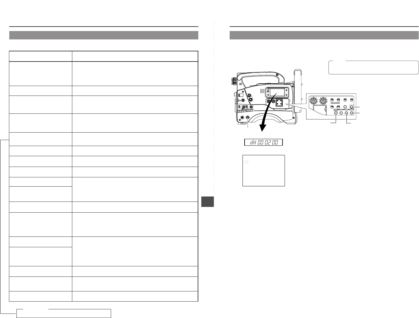
Counter display
Viewfinder
Accumulated drum running time: 200 hrs.
MENU button
2. 5.
5.
DATA SET button
4.
SELECT button
3.
GROUP button
1.
POWER switch
LIGHT
ON
OFF
COUNTER
CTL
TC
UB
RESET
OPERATE/WARNING
MONITOR
SELECT
STATUSSHUTTER
MENU
FILTER
1 3200k
2 5600k
3 5600k+ND
POWER
NG
GAIN
OUTPUT
WHT.BAL
VTR
ON OFF
ALARM
MONITOR
CH-1
CH-2
AUDIO
LEVEL
AUTO IRIS LOLUX
BACK L
NORMAL
SPOT L
STRETCH
NORMAL
COMPRESS
FULL AUTO BLACK
H
M
L
SAVE STBY
BA
RS CAM
ON
OFF
A
U
T
O
K
N
E
E
P
R
S
T
A
B
(HOUR METER)
DH :DRUM HOUR METER
000200H
TC GENERATOR
FREE
REC
PRESET
REGEN
CH-1
CH-2CH-1
CH-2
CH-1 CH-2
CONTINUE MENU
PRESETADVANCESHIFTHOLD
AUTO
MANUAL
FRONT
REAR
DATA SET
SELECTITEMGROUP
AUDIO SELECT
AUDIO INPUT
AUDIO
LEVEL
LITHIUM BATT.
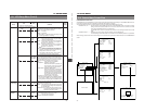
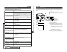
The unit can display the accumulated running time of the head drum as hour meter data on the counter display. The hour meter can
be displayed by selecting HM (HOUR METER) on the VCR Setup Menu. Use this as a guide for periodical maintenance.
☞ See page 7.
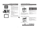
1.
Set the POWER switch to ON.
2.
Press the MENU button to display the VCR Setup Menu.
"MENU" lights in the display, and the VCR Setup Menu's
group menu appears in the viewfinder and on the counter
display.
3.
Press the GROUP button and choose "HM: HOUR METER".
• "HM HOUR METER" is shown blinking in the viewfinder.
The counter display shows "Hour".
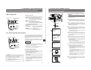
4.
Press the SELECT button.
The accumulated running time of the head drum is indicated
in the viewfinder and on the counter display.
5.
To return to the normal mode, press the DATA SET button.
• Pressing the MENU button returns you to the group menu.
14-2 Hour Meter Display
Note:
The hour meter is not shown correctly when no
videocassette is inserted.