


9
1. INTRODUCTION
8
1. INTRODUCTION
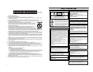
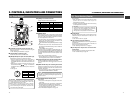
Head drum
Video tape
Monitor screen
Smear
(Vertical pale streaking
appearing at high
luminous object)
High luminous object
(Electric light, sunlight, etc.)
Blooming
(Blurring in highlight)
The GY-DV500 can use any of the following battery packs.
●
Flat shape type
●
Anton-Bauer battery pack: Trimpack 13/14 Series
Magnum 13/14 Series
Compack 13/14 Series
Propack 13/14 Series
* An Anton-Bauer battery pack cannot be connected directly
to the camera. It is necessary to mount the optional battery
holder.
●
Battery holder: Anton-Bauer QRQ27
For details on how to mount the battery holder, see page
37.
●
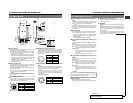
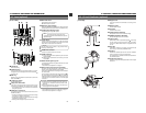
If the unit has been cooled down in a cold place and is then
carried to a warm place, the moisture contained in the warm
air may adhere to the head drum or tape guides and be cooled
into water droplets. This phenomenon is referred to as
condensation (dewing). When this occurs, the head drum and
tape guides are covered with droplets allowing the tape to be
stuck to them, leading to tape damage.
●
Condensation occurs in the following cases:
●
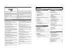
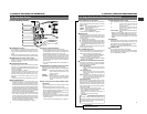
When condensation occurs in this unit, the DEW indicator
on the display lights up, and the WARNING LED blinks red.
(See page 86)
To remedy, leave the unit with the power ON and wait until
the WARNING LED stops blinking red and the DEW indicator
disappears from the counter display.
• When the unit is suddenly
moved from a cold place to a
warm place.
• When a room heater has just
started or when the unit is
exposed directly to cold air from
an air conditioner.
• When the unit is placed in a very
humid place.
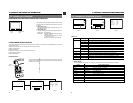
1-5 Battery Pack to be Used
To display the remaining battery power accurately, set the
VCR Setup Menu item No. 396 BATTERY TYPE according
to the type of the battery pack in use. (See page 69)
1-6
Condensation
Smear and Blooming
Due to the physical structure of a CCD it is possible to induce
vertical streaking (called "smear") when shooting an extremely
bright light source. Another effect is the expansion of light around
a bright light or object (called "blooming").
The CCD employed in this unit is characterized by inducing
very little smear or blooming. Nevertheless, please be careful
when shooting a bright light source.
Moire or Aliasing
Shooting stripes or fine patterns may cause a jagged effect or
a banding in fine mesh patterns.
White dots
High temperatures can cause CCD sensor pixels to malfunction
with the effect of white dots in the image. This condition is
conspicuous especially when gain is applied.
This is a characteristic of the charged-coupled device (CCD).
As far as possible, use the unit under conditions where the
temperature of the unit does not increase.
1-7 Characteristic CCD Phenomena
DEW
indicator
AUD LOCK
32k
CH 1
CH 2
48k
PB NDF
AUTO OFF DEW
HOLD
SP
MENU
OVER
OVER
40 30 20 10 0
dB
OPERATE/WARNING
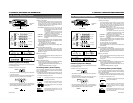
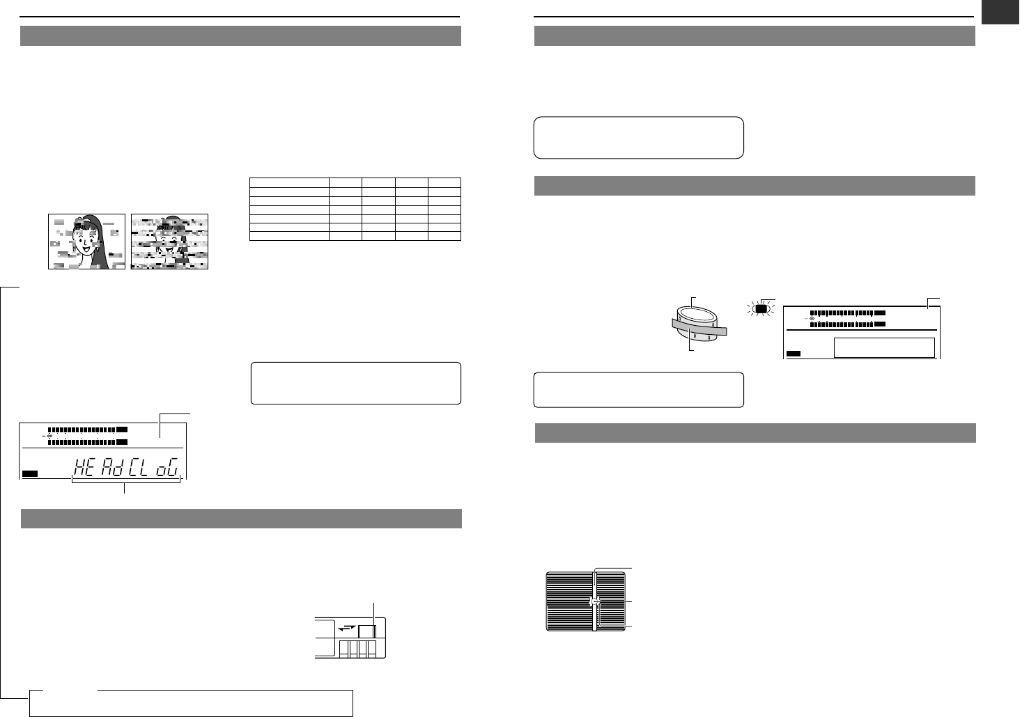
Head Cleaning
●
To maintain beautiful pictures and sound, be sure to use a
head cleaning tape to clean the head periodically. (Read the
separate sheet “Precautions for Use of Head Cleaning Tape”.)
If head cleaning is not performed periodically, a type of mosaic
noise called block noise may appear in the picture or sound
may be interrupted.
●
Use the provided head cleaning tape. Do not use head
cleaning tapes other than specified. For instructions on how
to use the head cleaning tape and precautions for its use,
read the separate sheet “Precautions for Use of Head
Cleaning Tape”.
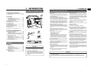
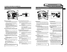
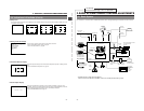
●
When dirt adheres to the heads of the GY-DV500, the
following indications appear during playback and recording
check using the RET button on the lens section.
• “RF” appears on the display panel.
• “HEAD CLOG” appears on the counter display.
• “VTR WARNING (HEAD)” appears in the viewfinder.
● If this kind of indication appears, please stop the recording.
Head cleaning is required. This indicator disappears when the
POWER is turned OFF, or when the cleaning tape is played
back.
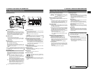
The GY-DV500 incorporates precision mechanical parts, which will collect dirt, wear out and deteriorate as the unit is used. On the
other hand, when the unit has been used for a long period in a normal environment, the heads, drums and tape transport mechanisms
also collect dirt deposited on them. Furthermore, dust which penetrates the inside of the VCR section especially during outdoor use
will promote the wear and deterioration of mechanical parts by causing poor contact between tape and heads or failing to maintain
the video and audio quality at high levels. To prevent wear and deterioration, clean the mechanical parts using a head cleaning tape
as routine maintenance. However, cleaning with a head cleaning tape alone is not enough for cleaning the entire tape transport
mechanism, it is also recommended to apply periodical maintenance (inspection) to prevent troubles that may be caused by the
sudden occurrence of failure. As the replacement, adjustment and servicing of parts require advanced skill and equipment, please
consult the person in charge of professional video equipment at your nearest JVC-authorized service agent.
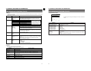
1-3 Routine and Periodical Maintenance
Periodical Maintenance
Contents : Check or replace the following mechanical parts
according to the running time.
• The maintenance contents vary depending on the operating
environment and method. Therefore, the above data should be
considered as a reference.
Time management
The accumulated running time of the unit can be confirmed
with the hour meter display (which shows the accumulated drum
running time). For details, see "HOUR METER DISPLAY" on
page 92.
For consultations related to the maintenance programming
or cost, please contact the person in charge of professional
video equipment at your nearest JVC-authorized service
agent.
⅜: Clean, check and adjust.
ଁ: Clean and check. Replace as required.
ⅷ: Replace.
Running Time
500H
1000 H 1500H
2000H
Drum ass’y (including heads)
⅜⅜⅜ⅷ
Head cleaner ଁⅷଁⅷ
Tape guides & rollers ⅜ଁଁⅷ
Rotary encoder – ଁ – ⅷ
Belts & gears ଁⅷଁⅷ
Drive parts ⅜⅜ଁⅷ
Block Noise
AUD LOCK
32k
CH 1
CH 2
48k
RF
SP
MENU
OVER
OVER
40 30 20 10 0
dB
"HEAD CLOG" indicator
"RF" indicator
REC
SAVE
Switch
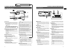
● Use JVC’s videocassette tapes marked with MiniDV for
this unit.
● Videocassettes cannot be used upside down.
● Avoid storing a videocassette with unevenly wound tape,
as this may damage the tape. Rewind it to the beginning
before placing a cassette into storage.
● Store videocassettes in a place with little humidity and good
ventilation where mould does not form.
● After a videocassette tape has been used repeatedly,
it becomes unable to maintain full performance due to
an increase in noise caused by dropouts, etc. Do not
continue to use a dirty or damaged tape, as this will
reduce the rotary head life.
● Note that if an ME80 videocassette is used at low
temperatures, block noise tends to occur due to head
contamination.
1-4 Videocassette to be Used
● Videocassette tapes marked MiniDV are provided with
a switch on the back for use in preventing accidental
erasure.
● Slide the switch to SAVE to protect the required recording
in the tape from being overwritten.
● To record on the tape, slide the switch to REC.
Do not leave the videocassette inserted when moving the
camera under conditions where the temperature
environment changes.
For servicing
See the service manual page 2-7 “2.4.3 Cleaning”.
For the part No. of cleaning tape, see section “7.1 PACKING” on this service manual.
→