


63
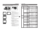
10. S.S.F. (Super Scene Finder) FUNCTION
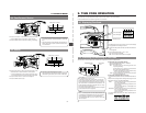
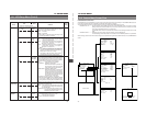
About the Scene End Cue Up Function
Ⅲ When the CONTINUE button is pressed while the LOG
button is kept pressed in the stop mode, the tape winds
to the S.S.F. data’s last OUT point, after which the unit
enters the record-pause mode. (Scene End Cue Up)
The FF button’s LED blinks during the Scene End Cue
Up mode.
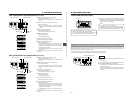
S.S.F. data stored in the unitís memory can be written to the
beginning of tape.
1.
Press the STOP button to enter the stop mode.
2.
Press the REW button while the LOG button is kept pressed.
• The REW indicator blinks during tape transport in the
writing position.
• The LOG indicator lights while S.S.F. data are being
written to the tape.
• When writing to the tape is completed, the LOG indicator
goes out.
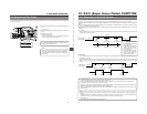
The S.S.F. data stored in the unit's memory can be output by
RS-232C control via the VTR REMOTE connector.
LIGHT
ON
OFF
COUNTER
CTL
TC
UB
RESET
OPERATE/WARNING
MONITOR
SELECT
STATUSSHUTTER
MENU
FILTER
1 3200k
2 5600k
3 5600k+ND
POWER
NG
GAIN
OUTPUT
WHT.BAL
VTR
ON OFF
ALARM
MONITOR
S
A
V
E
S
T
B
Y
H
M
L
B
A
R
S
C
A
M
A
U
T
O
K
N
E
E
P
R
S
T
A
B
O
N
O
F
F
CH-1
CH-2
AUDIO
LEVEL
AUTO IRIS LOLUX
BACK L
NORMAL
SPOT L
STRETCH
NORMAL
COMPRESS
FULL AUTO BLACK
TC GENERATOR
FREE
REC
PRESET
REGEN
CH-1
CH-2CH-1
CH-2
CH-1 CH-2
CONTINUE MENU
PRESETADVANCESHIFTHOLD
AUTO
MANUAL
FRONT
REAR
DATA SET
SELECTITEMGROUP
AUDIO SELECT
AUDIO INPUT
AUDIO
LEVEL
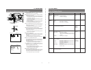
LITHIUM BATT.
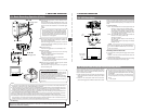
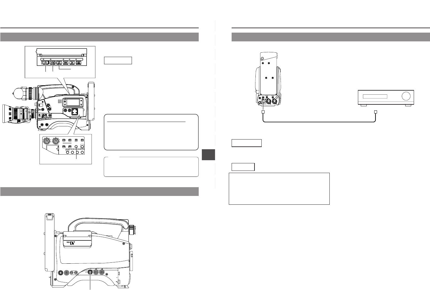
CONTINUE button
LOG REW FF
PLAY STILL
STOP
2.
LOG button
2.
REW button
1.
STOP button
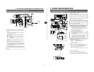
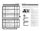
10-6 Outputting S.S.F. Data
Operation
VTR
REMOTE
SYNC IN
MIC IN
LENS
TEST OUT
Y/C OUT MONITOR OUT
LINE OUT
CH-1 CH-2
PUSH
DV CAMCORDER
GY-DV500
VTR REMOTE connector
10-5 Writing S.S.F. Data to Tape
Note:
Once a tape with recorded S.S.F. data is ejected and then
reinserted again, the previous data will be erased if new
S.S.F. data are recorded on the tape.
64
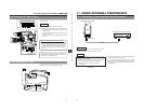
11. USING EXTERNAL COMPONENTS
TALLY
DV
AUDIO IN
CH-1
DC INPUT
EARPHONE
DC OUTPUT
LINE MIC
+48V
ON
CH-2
LINE MIC
+48V
ON
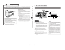
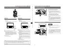
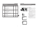
Rear section of GY-DV500
DV connector
DV cable
DV connector
Video component with DV Connector
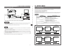
11-1 Connecting a Video Component with DV Connector
Connection
Connect the DV connector on the GY-DV500 to the DV
connector on the video component using the DV cable.
Settings
Ⅲ Recording the playback image or audio of the GY-DV500 on
the video component with DV connector
• To remote control the playback operation of the GY-DV500
from the video component with DV connector, set the VCR
Setup Menu item No. 050 REMOTE SELECT to "IEEE1394".
☞ See page 68.
Ⅲ Recording the image of the video component with DV
connector on the GY-DV500
• To input the image via the DV connector, set the VCR Setup
Menu item No. 126 INPUT SELECT to "IEEE1394".
* Settings cannot be changed during recording.
☞ See page 68.
↑
U-ver. only