


27
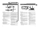
2. CONTROLS, INDICATORS AND CONNECTORS
26
2. CONTROLS, INDICATORS AND CONNECTORS
1
7
2
3
4
5
6
C
8
7
9
0AB
1
2
3
4
5
6
SCENE F I LE
WHITE B A L A
A
FILTER
SHUTTER 1/10
3.2K
00
GA IN 6 dB
IRIS LEVEL NORMAL
I R I S DETECT NORMAL
FULL AUTO OFF
REC T IME <60
ACCU -FOCUS
G
F
I
B
SD
ACCU -FOCUS
G
F
I
F5.6
STBY 4V21.<60
B
CH1 ----+--
CH2 ----+--
SD
M909
●
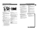
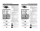
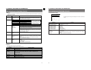
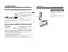
Status 0
Display Position
Display Function
1
ACCU-FOCUS Blinks during the ACCU-FOCUS operation.
SKIN AREA Blinks while the skin tone detail color area is displayed.
S Displayed when the SHUTTER or V-SCAN is ON.
FAS Displayed when the Full Auto Shooting is ON.
ALC Displayed when the ALC alone is ON.
2
G Displayed in other modes than 0 dB, LOLUX and ALC.
L Displayed during LOLUX operation.
3
F Displayed when FAW alone is ON.
4
I Displayed when IRIS BACK LIGHT or IRIS SPOT LIGHT is selected.
5
SD Displayed while the Skin Detail function is in operation.
6
B Displayed when BLACK STRETCH or BLACK COMPRESSION is selected.
7
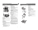
Event display See the table below.
Switch
Event Display Contents
ZEBRA ZEBRA ON, OFF
BLACK BLACK STRETCH, NORMAL, COMPRESS
GAIN GAIN –3 dB, 0 dB, 6 dB, 9 dB, 12 dB, 18 dB, ALC
WHT. BAL WHITE BAL A, B, PRESET, FAW
FULL AUTO FULL AUTO ON, OFF
AUTO IRIS IRIS BACK.L, NORMAL, SPOT.L
LOLUX LOLUX ON, OFF
FILTER knob FILTER 3.2K, 5.6K, 5.6K+ND
VTR VTR STBY, SAVE
AUTO KNEE AUTO KNEE ON, OFF
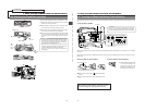
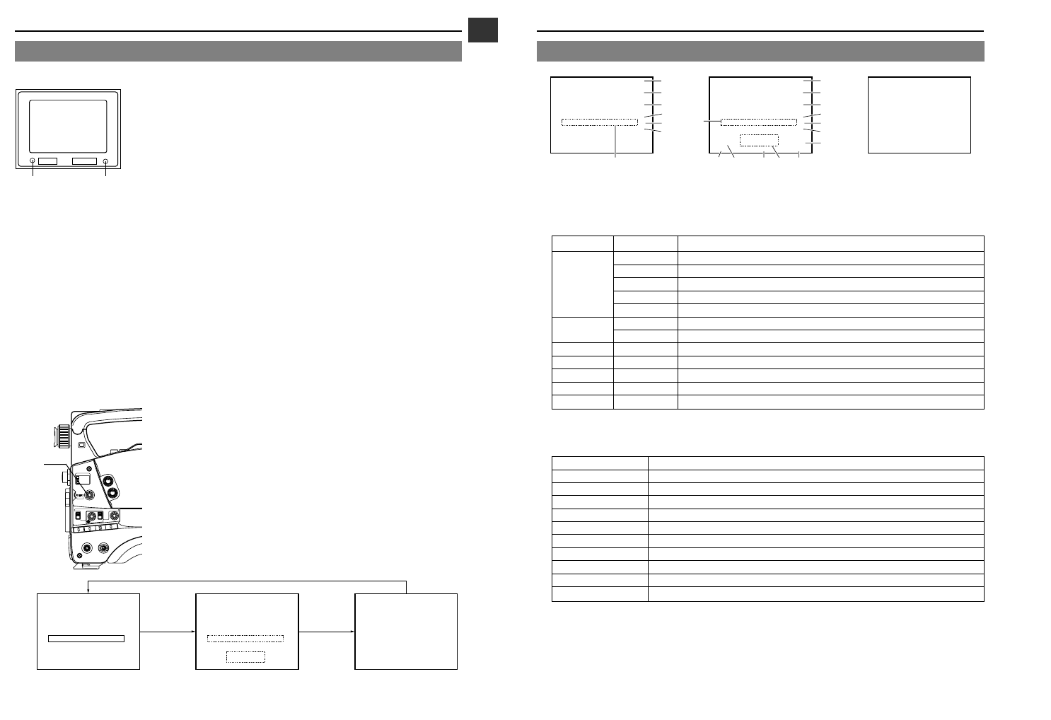
7 Event display
Event is displayed in the viewfinder for only about 2 seconds when any of the following switches is operated.
2-9 Indications in Viewfinder (Cont'd)
Status 0 Status 1 Status 2
BATT ALARM
REC
BATT
Lamp
REC/ALARM
Lamp
ACCU -FOCUS
G
F
I
SD
B
ACCU
M909
-FOCUS
G
F
I
F5.6
STBY 4V21.<60
B
CH1 ----+--
CH2 ----+--
SCENE F I LE
WHITE B A L A
A
FILTER
SHUTTER 1/10
3.2K
00
GA IN 6 dB
IRIS LEVEL NORMAL
I R I S DETECT NORMAL
FULL AUTO OFF
REC T IME <60
SD
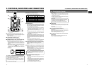
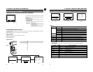
The viewfinder has two LED indicators below the screen. These
LEDs light or blink to indicate the present status of the camera
or the VCR.
●
[BATT] battery lamp
This lights red when the battery voltage becomes too low for
operating the camera.
●
REC/ALARM lamp
This lights or blinks green under the following circumstances.
Steady green : During recording.
Blinks green : • While the GY-DV500 switches from record-
pause to recording.
• Immediately before the tape is running out
or when it has run out.
• When an error occurs in the GY-DV500.
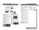
2-9 Indications in Viewfinder
Ⅲ WARNING LED INDICATORS INSIDE THE VIEWFINDER
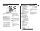
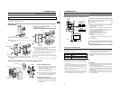
Ⅲ VIEWFINDER SCREEN DISPLAY
The following indications are displayed on the viewfinder screen. (However, this information is not displayed while the VCR section
is playing back a tape.)
Ⅲ Status screens (screens for use in checking the current camera settings)
Ⅲ Alarm message display
Ⅲ Safety zone display
Ⅲ Setting screen (screen for use in the camera and VCR setup)
Ⅲ Auto white balance display
Ⅲ Shutter speed display
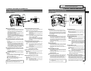
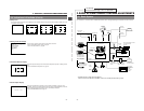
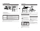
Ⅲ Status Screens
Status 0 Status 1 Status 2
LIGHT
ON
OFF
COUNTER
CTL
TC
UB
RESET
OPERATE/WARNING
MONITOR
SELECT
STATUSSHUTTER
MENU
FILTER
1 3200k
2 5600k
3 5600k+ND
POWER
NG
G
A
IN
O
U
T
P
U
T
W
H
T
.B
A
L
V
TR
ON OFF
ALARM
MONITOR
S
A
V
E
S
T
B
Y
H
M
L
B
A
R
S
C
A
M
AUTO K
NEE
PRST A B
ON
OFF
CH-1
CH-2
AUDIO
LEVEL
AUTO IRIS LOLUX
BACK L
NORMAL
SPOT L
STRETCH
NORMAL
COMPRESS
FULL AUTO BLACK
STATUS
button
Press the STATUS button during normal screen display to show one of the status
screens in the viewfinder. One of the three status screens will be displayed every
time the button is pressed.
25 26