


65
11. USING EXTERNAL COMPONENTS
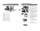
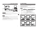
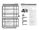
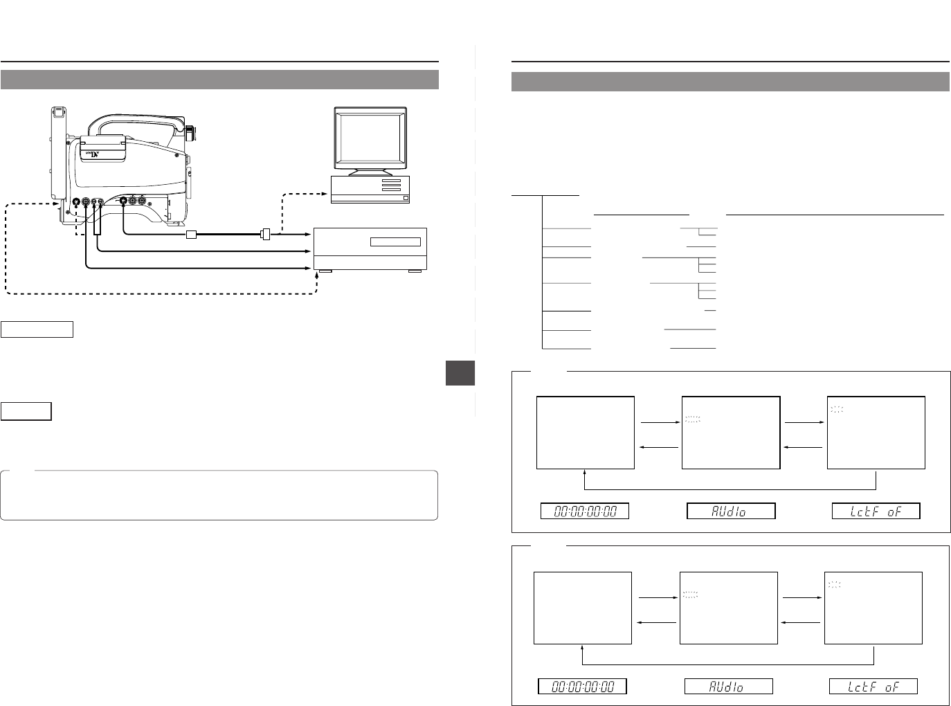
11-2 Connecting a PC
VTR
REMOTE connector
TTL RS-232C
converter cable
(Optional VC-P893)
AUDIO OUT
DV connector
AUDIO IN
VIDEO IN
PC
RS-232C
RS-232C
Non-linear editing controller
DV connector
MONITOR
OUT
connector
VTR
REMOTE
SYNC IN
MIC IN
LENS
TEST OUT
Y/C OUT MONITOR OUT
LINE OUT
CH-1 CH-2
PUSH
DV CAMCORDER
GY-DV500
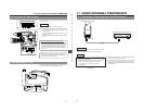
Connections
Connect the GY-DV500's VTR REMOTE connector to the RS-232C connector on the PC or the non-linear editing controller using
the TTL ⇔ RS-232C converter cable.
Or connect the GY-DV500’s DV connector and the DV connector of the non-linear editing controller using a DV cable.
For compatible non-linear editing controller, consult with your JVC dealer.
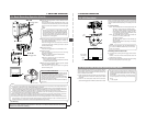
Settings
• To remote control the PC or non-linear editing controller by means of RS-232C, set the VCR Setup Menu item No. 050 REMOTE
SELECT to "RS232C". ☞ See page 68.
• To remote control the GY-DV500’s VCR using the DV connector’s IEEE1394 option, set the VCR Setup Menu item No. 050
REMOTE SELECT to “IEEE1394”. ☞ See page 68.
Ⅲ The S.S.F. data stored in the unit's memory is output from the VTR REMOTE connector.
Note:
• When a cable is connected to the VTR REMOTE connector, the VTR Setup Menu is not displayed in the viewfinder. Make
settings on the VTR Setup Menu while the cable is not connected.
• When a cable is connected to the VTR REMOTE connector, the VCR operation mode will not be displayed correctly on the
Status1 screen in the viewfinder.
66
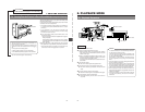
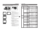
12. SETUP MENU
The setup menus for the VCR section can be set while observing the menu in the viewfinder and on the unit's counter display.
The set contents are stored in the memory and retained even after the power is switched OFF.
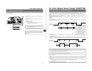
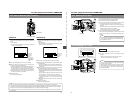
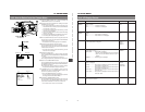
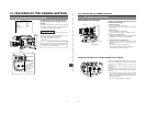
VCR SETUP MENU CONFIGURATION
The VCR Setup Menu is a two-layer construction.
The VCR Setup Menu consists of seven group menus divided according to functions. When a Group menu is selected, the menu's
Item menu opens. Each Item menu contains one or several items, and the various items can be set individually as required.
Normal screen
Viewfinder display
Counter display
Group Menu
DATA SET button
MENU button
MENU button
Item Menu
(example: AUDIO)
SELECT button
MENU button
000 :SERVO/SYSTEM
100 :VIDEO
200 :AUDIO
300 :SYSTEM
400 :TIME CODE
500 :ON SCREEN
HM :HOUR MET ER
244:LOW CUT
OFF
245:SAMPLE RATE
48K
246:FRONT VOLUME
ENABLE
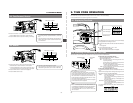
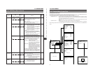
12-1 VCR Setup Menu
SERVO/SYSTEM
VIDEO (U-ver. only)
AUDIO
SYSTEM
TIME CODE (U-ver. only)
ON SCREEN
HOUR METER
000
100
200
300
400
500
HM
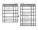
Selection of remote control to control the unit
Selection of BACK TALLY lamp lighting pattern
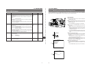
Selection of video input
Selection of low cut for audio input signals
Selection of sampling frequency for audio input signals
Selection of front section audio volume control
Selection of long pause/still duration
Selection of battery type
Selection of S.S.F. (Super Scene Finder) mode
Selection of time code framing mode
Selection of counter display method (Time code/Date/Time)
Display of hour meter (accumulated running time of head drum)
VCR Setup Menu
Group Name Item Menu Contents
Normal screen
Viewfinder display
Counter display
Group Menu
DATA SET button
MENU button
MENU button
Item Menu
(example: AUDIO)
SELECT button
MENU button
000 :SERVO/SYSTEM
100 :VIDEO
200 :AUDIO
300 :SYSTEM
400 :TIME CODE
500 :ON SCREEN
HM :HOUR MET ER
244:LOW CUT
OFF
245:SAMPLE RATE
48K
246:FRONT VOLUME
ENABLE
U-ver.
E-ver.