


67
12. SETUP MENU
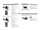
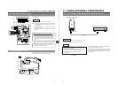
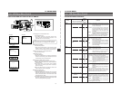
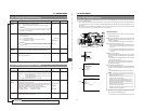
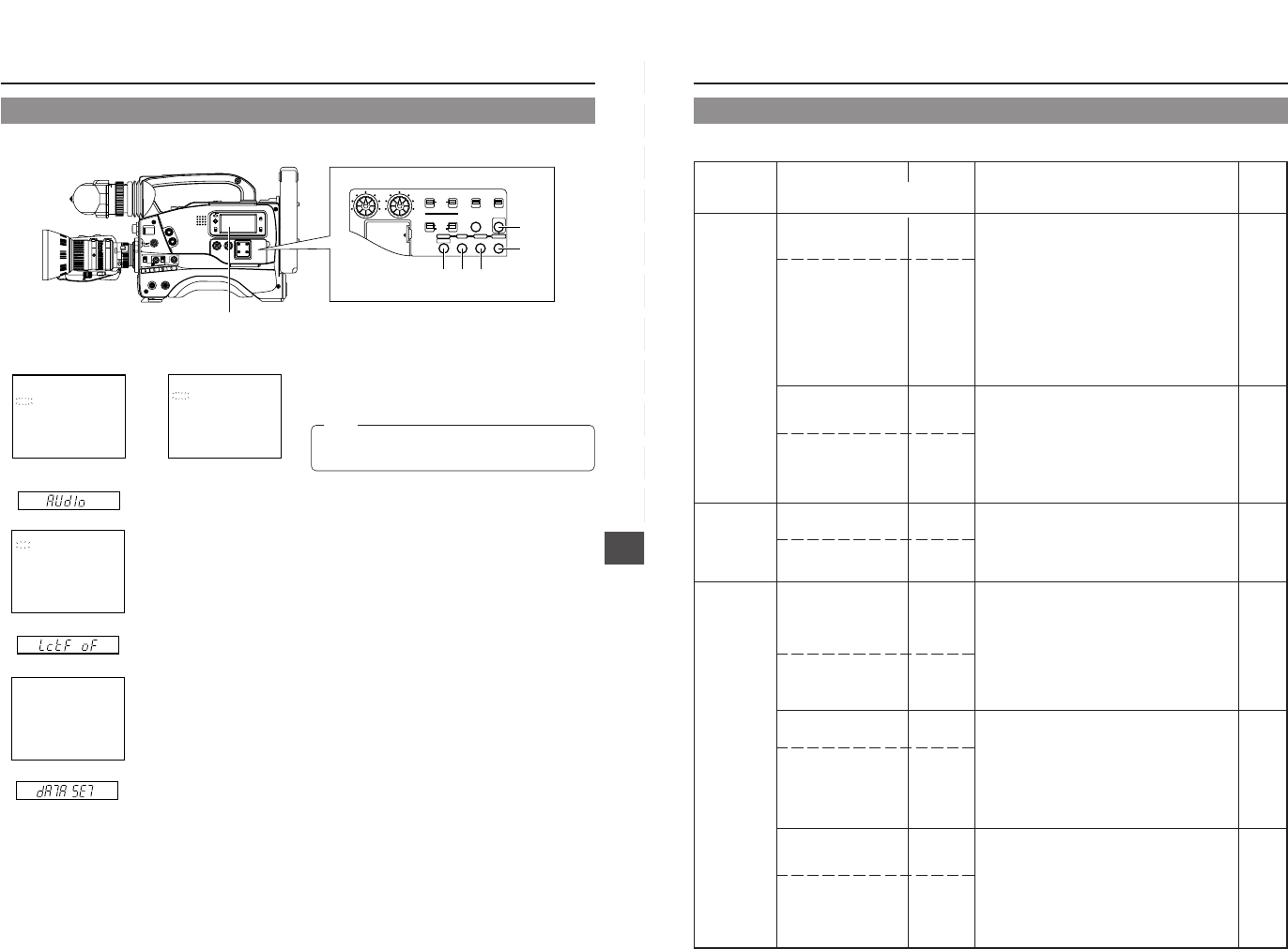
DISPLAYING AND SETTING VCR SETUP MENUS
1.
Engaging the VCR Setup Menu mode.
Press the MENU button.
• The "MENU" indication in the display section starts
blinking and the VCR Setup Menu appears in the
viewfinder and on the counter display.
2.
Selecting the GROUP.
Press the GROUP button.
• Each time the GROUP button is pressed the selected
GROUP number is shown blinking on the viewfinder
screen. The counter display shows the selected group.
3.
Open the Item menu of the selected GROUP.
Press the SELECT button.
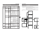
4.
Selecting the Item.
Press the ITEM button.
• Each time the ITEM button is pressed the selected item
number is shown blinking on the viewfinder screen. The
counter display shows the selected item.
5.
Changing the setting value of the item.
Press the SELECT button and select the setting value.
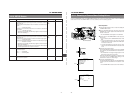
Ⅲ When multiple items should be set, repeat the operations
of steps
4.
and
5
.
Ⅲ To set menu items in other groups, press the MENU
button. When the relevant group menu is displayed,
perform the setting.
Ⅲ When the GROUP button is pressed, the items of the
higher order group menu are displayed.
6.
Saving the setting value.
Press the DATA SET button.
• "DATA SET" appears in the viewfinder and on the counter
display and the setting value is saved in the GY-DV500's
memory. The display returns to the normal screen mode
when data has been saved.
Ⅲ If the MENU button is pressed without pressing the DATA
SET button, the display returns to the normal screen mode
without the setting value being changed.
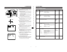
GROUP menu screen for U-ver.
Viewfinder
Item menu screen
DATA SET display
Counter display
000 :SERVO/ SYSTEM
100 :VIDEO
200 :AUDIO
300 :SYSTEM
4 00 : T I ME CODE
500 :ON SCREEN
HM :HOUR METER
244:LOW CUT
OFF
245:SAMPLE RATE
48K
2 46 : FRONT
DATA SET
VOLUME
ENABLE
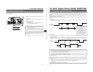
12-1 VCR Setup Menu (Cont'd)
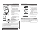
LIGHT
ON
OFF
COUNTER
CTL
TC
UB
RESET
OPERATE/WARNING
MONITOR
SELECT
STATUSSHUTTER
MENU
FILTER
1 3200k
2 5600k
3 5600k+ND
POWER
NG
G
A
IN
O
U
T
P
U
T
W
H
T
.B
A
L
V
T
R
ON OFF
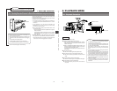
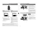
ALARM
MONITOR
CH-1
CH-2
AUDIO
LEVEL
AUTO IRIS LOLUX
BACK L
NORMAL
SPOT L
STRETCH
NORMAL
COMPRESS
FULL AUTO BLACK
H
M
L
S
AV
E
S
T
BY
BA
RS
CA
M
O
N
O
F
F
A
U
T
O
K
N
E
E
P
R
S
T
A
B
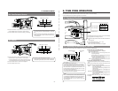
TC GENERATOR
FREE
REC
PRESET
REGEN
CH-1
CH-2CH-1
CH-2
CH-1 CH-2
CONTINUE MENU
PRESETADVANCESHIFTHOLD
AUTO
MANUAL
FRONT
REAR
DATA SET
SELECTITEMGROUP
AUDIO SELECT
AUDIO INPUT
AUDIO
LEVEL
LITHIUM BATT.
"MENU" indication
2. 3. 5.4.
6.
1.
Note:
When a cable is connected to the VTR REMOTE connector,
the VTR Setup Menu is not displayed in the viewfinder.
GROUP menu screen for E-ver.
Viewfinder
000 :SERVO/ SYSTEM
200 :AUDIO
300 :SYSTEM
500 :ON SCREEN
HM :HOUR METE R
68
12. SETUP MENU
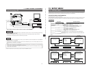
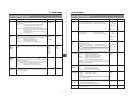
Group
Item
Setting
Contents
Factory
Value
Setting
Upper row: Viewfinder display
Lower row: Counter display indication
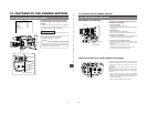
VCR SETUP MENU CONTENTS
SERVO
/SYSTEM
VIDEO
(U-ver. only)
AUDIO
050: REMOTE SELECT
rnSL
082: BACK TALLY MODE
rtMd
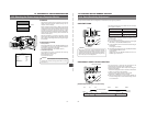
126: INPUT SELECT
vld
244: LOW CUT
LctF
245: SAMPLING RATE
snPL
246: FRONT VOLUME
ENABLE
FruL
LOCAL
IEEE1394
RS232C
Lc
IE
23
OFF
ON
BLINK
oF
on
bL
CAMERA
IEEE1394
cA
IEEE1394
OFF
CH1
CH2
CH1 &
CH2
oF
01
02
on
32K
48K
32
48
DISABLE
ENABLE
oF
on
Selection of the method for remote control of the VCR.
LOCAL : Choose this setting when the VCR should
be controlled using the operation buttons
on the GY-DV500 only.
IEEE1394: Choose this setting when the VCR should
be remote controlled from a DV connector
equipped video component connected to
the DV connector on the rear section of the
GY-DV500.
RS232C : Choose this setting for control by means of
the VCR remote control signal from the VTR
REMOTE connector on the GY-DV500.
* The operation buttons on the GY-DV500 remain
effective even when set to IEEE1394 or RS232C.
Selection of the lighting pattern of the BACK TALLY lamp
on the rear section during recording.
OFF : The lamp is always off.
ON : The lamp lights during recording. It remains
off until the VTR trigger button is pressed
to start the recording.
BLINK : The lamp lights during recording. It blinks
when the VTR trigger button is pressed to
start the recording.
Selection of the input video signal.
Settings cannot be changed during recording.
CAMERA : Camera image is input.
IEEE1394: The image from the DV connector equipped
video component connected to the DV
connector on the rear section is input.
To select whether or not the low frequencies of the audio
signal from the audio input connectors are cut. Set to
ON to reduce the wind noise of the microphone.
OFF :
The CH1 and CH2 low frequencies are not cut.
CH1 : Only the low frequencies of the audio signal
input to the CH1 channel are cut.
CH2 : Only the low frequencies of the audio signal
input to the CH2 channel are cut.
CH1& CH2
:The low frequencies are cut for both CH1
and CH2.
To select the sampling rate for digital PCM audio recording.
32K : Digital recording occurs with 12-bit, 32 kHz
sampling
48K : Digital recording occurs with 16-bit 48 kHz
sampling.
* The DV format offers recording tracks for up to 4
channel when recording using 12-bit, 32 kHz
sampling. The GY-DV500 records two of these tracks.
The GY-DV500 does not allow after-recording.
To select whether or not the front section recording level
control should be operative. The front section recording
level control only affects the audio signal recorded on CH1.
DISABLE : Use of the front section recording level
control is disabled.
ENABLE : Use of the front section recording level
control is enabled.
* The CH-1 recording level control on the side section
works regardless of the setting.
LOCAL
BLINK
CAMERA
OFF
48K
ENABLE
12-1 VCR Setup Menu (Cont'd)