


15
2. CONTROLS, INDICATORS AND CONNECTORS
14
2. CONTROLS, INDICATORS AND CONNECTORS
LIGHT
ON
OFF
COUNTER
CTL
TC
UB
RESET
OPERATE/WARNING
MONITOR
SELECT
STATUSSHUTTER
MENU
FILTER
1 3200k
2 5600k
3 5600k+ND
POWER
NG
GAIN
OUTPUT
W
HT.BAL
VTR
ON OFF
ALARM
MONITOR
CH-1
CH-2
AUDIO
LEVEL
AUTO IRIS LOLUX
BACK L
NORMAL
SPOT L
STRETCH
NORMAL
COMPRESS
FULL AUTO BLACK
H
M
L
S
A
V
E
S
T
B
Y
B
A
R
S
C
A
M
O
N
O
F
F
A
U
T
O
K
N
E
E
P
R
S
T
A
B
TC GENERATOR
FREE
REC
PRESET
REGEN
CH-1
CH-2CH-1
CH-2
CH-1 CH-2
CONTINUE MENU
PRESETADVANCESHIFTHOLD
AUTO
MANUAL
FRONT
REAR
DATA SET
SELECTITEMGROUP
AUDIO SELECT
AUDIO INPUT
AUDIO
LEVEL
LITHIUM BATT.
qy
w
ui
o
ert
1
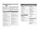
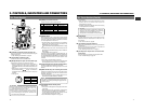
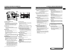
[MENU] button
Press this button to enter the VCR setup menu mode.
When the VCR setup menu mode is engaged, the "MENU"
indicator in the LCD display lights and the counter display
and viewfinder display are changed to the menu indication.
In the VCR setup menu mode, pressing this button resumes
the normal mode.
2
[HOLD/GROUP] button
• Press this button when presetting the time code or user's
bit. The presently displayed data is held (the "HOLD"
indicator lights on the display) and the leftmost digit of
the counter blinks. Pressing this button during presetting
of time code or user's bit cancels the operation and recalls
the previous display contents.
• In setup menu mode, this button is used to select the
menu group.
3
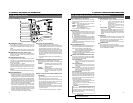
[SHIFT/ITEM] button
• During presetting of time code or user's bit, press this
button to select the digit to be set. Each press of the button
shifts the digit to be set (which blinks) to the right.
• In setup menu mode, this button is used to select the
menu item.
4
[ADVANCE/SELECT] button
• During presetting of time code or user's bit, press to select
the value of the digit to be set. Each press of the button
increases the number by 1.
• In setup menu mode, this button is used to select the
value of a menu item.
5
[PRESET/DATA SET] button
• During presetting of time code or user's bit, press to save
the set value in the preset memory. The set time code or
user's bit will be preset in the time code generator.
• In setup menu mode, this button is used to confirm the
menu item setting and save the data in the memory.
• For details of the presetting of time code or user's
bit, see page 56.
• For details on the setup menus, see page 67.
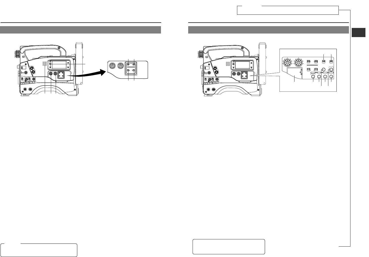
[VCR Setup Block]
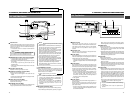
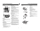
6
[CONTINUE] button
If this button is pressed simultaneously with the LOG button
8 on page 19 during the stop mode, the tape winds to the
last S.S.F. data OUT point.
☞
See “About the Scene End Cue Up Function” on page 63.
TIME CODE GENERATOR setting switches
7
[PRESET/REGEN] switch
Toggles the time code generator mode between PRESET
and REGEN.
PRESET: Preset mode. Set to this position when newly
presetting and recording the time code.
REGEN : Regeneration mode, in which the unit reads
existing time codes on the tape and records time
codes in continuation of the existing ones. Set to
this position when you want to add additional time
codes to time codes already recorded on the
tape.
8
[REC/FREE] run switch
Selects the time code running mode while the time code
generator is in preset mode. This switch is not effective in
the REGEN mode.
REC : The time code runs only during recording. This
position allows you to record continuous time
codes when recording scenes one after another.
FREE : The time code runs permanently.
*If this position is used when recording scenes one after
another, the time codes become discontinuous at the
change points between scenes.
9
Lithium Battery Installation Compartment
Install a lithium battery (CR2032) in this compartment. The
battery is used for the backup of the time code. The GY-
DV500 is delivered without the battery installed.
The provided lithium battery is for test use. It is recommended
to install a new lithium battery. A new lithium battery can
power the backup for about one year. See "Inserting and
Replacing Backup Lithium Batteries" on page 34.
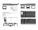
2-2 Right Side Section (Cont'd)
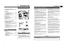
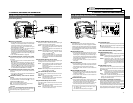
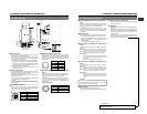
1
Monitoring loudspeaker
• Enables EE monitoring of the input audio signal during
recording, in the record-pause mode or in the stop mode.
Outputs the playback sound in the playback mode.
The sound to be output can be selected using the
MONITOR SELECT switch
4
.
• The loudspeaker volume can be adjusted with the
MONITOR volume control
2
on page 12.
The audio from the loudspeaker is not output when an
earphone is plugged into the EARPHONE jack
2
on page
20. The warning alarm tones are also output through this
loudspeaker.
☞ See “ALARM INDICATIONS” on pages 86.
2
[CH1 AUDIO LEVEL] CH1 recording level control
Adjust the recording level of the CH1 audio channel with
this control.
• To use this control, set the CH1 AUDIO SELECT switch
5 to “MANUAL”.
This control works regardless of the setting of the VCR
Setup Menu item No. 246 FRONT VOLUME ENABLE.
To use this control, set the AUDIO LEVEL CH-1 recording
level control (7 on page 10) on the front section to the
maximum (10) position, or set the VCR Setup Menu item
No. 246 FRONT VOLUME ENABLE to “DISABLE”.
3
[CH2 AUDIO LEVEL] CH2 recording level control
Adjust the recording level of the CH2 audio channel with
this control.
• This control is valid only when the CH2 AUDIO SELECT
switch
6
is set to "MANUAL".
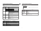
4
[MONITOR SELECT] audio monitor selector
switch
This switch is used to select the monitor sound output from
the MONITORING LOUDSPEAKER 1 or via the
EARPHONE jack 2 on page 20.
CH-1: The CH1 channel audio is output.
MIX : CH1 and CH2 channel audio are output mixed.
CH-2: The CH2 channel audio is output.
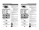
5
[CH-1 AUDIO SELECT] selector switch
This switch is used to select the method for adjusting the
recording level of the CH-1 audio channel.
AUTO :The recording level is held at the reference level
even when sounds greater than the reference
level are input.
The recording level does not increase when the
input level is low.
MANUAL
:The recording level can be adjusted with the CH-
1 AUDIO LEVEL control
2
or the CH-1 AUDIO
LEVEL control
7
on page 10.
To use the AUDIO LEVEL CH-1 recording level
control on the front section, set the VCR Setup
Menu item No. 246 FRONT VOLUME ENABLE
to “ENABLE”.
6
[CH-2 AUDIO SELECT] selector switch
This switch is used to select the method for adjusting the
recording level of the CH-2 audio channel.
AUTO :The recording level is held at the reference level
even when sounds greater than the reference
level are input.
The recording level does not increase when the
input level is low.
MANUAL
:The recording level can be adjusted with the CH-
2 AUDIO LEVEL control
3
.
7
[CH-1 AUDIO INPUT] selector switch
This switch is used to select the input section of the CH1
audio channel.
FRONT :The sound from the MIC IN connector on the
front side section is input.
REAR :The sound from the CH-1 AUDIO IN connector
on the rear side section is input.
8
[CH-2 AUDIO INPUT] selector switch
This switch is used to select the input section of the CH2
audio channel.
FRONT :The sound from the MIC IN connector on the
front side section is input.
REAR :The sound from the CH-2 AUDIO IN connector
on the rear side section is input.
[Audio Setting Section]
2-2 Right Side Section (Cont'd)
qwe
r
ty
ui
LIGHT
ON
OFF
COUNTER
CTL
TC
UB
RESET
OPERATE/WARNING
MONITOR
SELECT
STATUSSHUTTER
MENU
FILTER
1 3200k
2 5600k
3 5600k+ND
POWER
NG
GAIN
OUTPUT
WHT.BAL
VTR
ON OFF
ALARM
MONITOR
CH-1
CH-2
AUDIO
LEVEL
AUTO IRIS LOLUX
BACK L
NORMAL
SPOT L
STRETCH
NORMAL
COMPRESS
FULL AUTO BLACK
H
M
L
SA
V
E
S
TB
Y
B
A
R
S
C
A
M
O
N
O
F
F
A
U
T
O
K
N
E
E
P
R
S
T
A
B
CH-1
CH-2
AUDIO
LEVEL
CH-1 CH-2
AUTO
MANUAL
FRONT
REAR
AUDIO SELECT
AUDIO INPUT
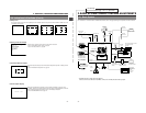
CAUTION:
Make sure to move switches all the way. Do not leave a
switch stopped in a midway position. Noise will be
generated and operation irregularities will occur.
For servicing
When replacing the Lithium Battery, see page 41 “Setting the Date and
Time” and then set the date and time as described therein.
←