


47
6. SETTING AND ADJUSTMENTS BEFORE SHOOTING
LIGHT
ON
OFF
COUNTER
CTL
TC
UB
RESET
OPERATE/WARNING
MONITOR
SELECT
STATUSSHUTTER
MENU
FILTER
1 3200k
2 5600k
3 5600k+ND
POWER
NG
G
A
I
N
O
U
T
P
U
T
W
H
T
.B
A
L
V
T
R
ON OFF
ALARM
MONITOR
CH-1
CH-2
AUDIO
LEVEL
AUTO IRIS LOLUX
BACK L
NORMAL
SPOT L
STRETCH
NORMAL
COMPRESS
FULL AUTO BLACK
H
M
L
SAV
E S
T
B
Y
B
ARS CAM
O
N
OFF
A
U
T
O
K
N
E
E
P
R
S
T
A
B
AUTO
WHITE
SKIN
AREA
ACCU
FOCUS
TAKE
VTR
ZEBRA
AUDIO
LEVEL CH-1
ON
OFF
VF
TALLY
DV
AUDIO IN
CH-1
DC INPUT
EARPHONE
DC OUTPUT
LINE MIC
+48V
ON
CH-2
LINE MIC
+48V
ON
CH-1
CH-2
AUDIO
LEVEL
CH-1 CH-2
AUTO
MANUAL
FRONT
REAR
AUDIO SELECT
AUDIO INPUT
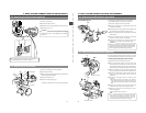
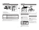
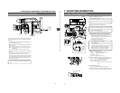
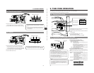
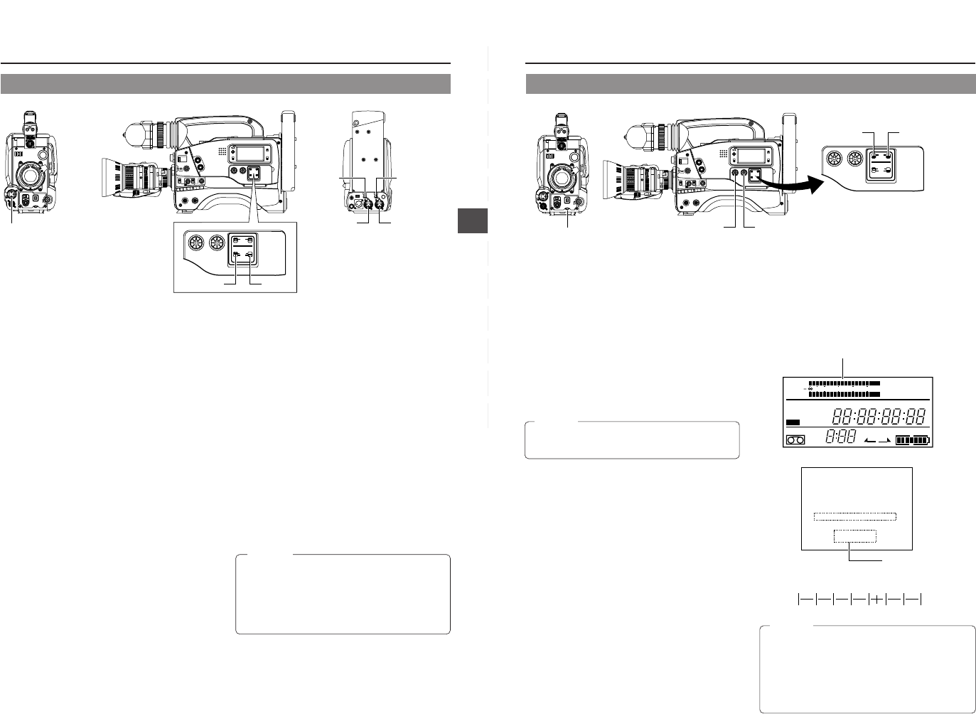
6-7 Audio Input Signal Selection
The GY-DV500 is provided with the microphone connector on
the front section and the two AUDIO INPUT connectors at the
rear section for audio input.
On the other hand, two channels of sound can be recorded on
the tape in digital PCM format.
Using the AUDIO INPUT switch, select for each channel (CH1
and CH2) whether the sound to be recorded should be the
sound from the microphone connector on the front section or
the sound from the AUDIO INPUT connectors on the rear
section.
Ⅲ Selecting the CH-1 channel input sound
Make the selection using the CH-1 AUDIO INPUT switch.
FRONT : The sound from the microphone connector on the
front section is recorded on the CH-1 channel.
REAR : The sound from the CH-1 AUDIO INPUT
connector on the rear section is recorded on the
CH-1 channel.
Ⅲ Selecting the CH-2 channel input sound
Make the selection using the CH-2 AUDIO INPUT switch.
FRONT : The sound from the microphone connector on the
front section is recorded on the CH-2 channel.
REAR : The sound from the CH-2 AUDIO INPUT
connector on the rear section is recorded on the
CH-2 channel.
Ⅲ Selecting the front section's microphone connector
A microphone (phantom microphone, etc.) requiring +48 V
power supply or other type of camera microphone
(monaural) can be connected.
• In accordance with the connected microphone, specify
the phantom microphone or other type of microphone
using the Camera Setup Menu item CAM MIC +48V.
• The reference input level is -60 dBs.
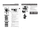
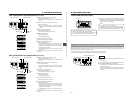
Ⅲ Selection of rear audio input connectors
Select the audio signal input to the AUDIO INPUT connector
using the [LINE/MIC] switch. Make settings for the CH-1
and CH-2 AUDIO IN connectors separately.
LINE : Set to this position when connected to audio
equipment, etc.
The reference input level is +4 dBs.
MIC : Set to this position when using a monaural
microphone.
The reference input level is -60 dBs.
MIC +48 V : Set to this position when a microphone
(phantom microphone) requiring +48 V DC
power supply is connected.
Microphone input
connector
CH-1 AUDIO
LINE/MIC
switch
CH-2 AUDIO
LINE/MIC
switch
CH-1 AUDIO
INPUT
connector
CH-2 AUDIO
INPUT
connector
CH-1 AUDIO
INPUT switch
CH-2 AUDIO
INPUT switch
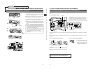
CAUTION:
When connecting a component that does not require
+48 V power supply, make sure that the LINE/MIC switch
is not set to MIC +48V.
When using the microphone on the front section, set the
Camera SETUP screen item “CAM MIC +48V” to “OFF”.
Neglecting this could cause damage to the connected
component. ☞ See page 77.
48
6. SETTING AND ADJUSTMENTS BEFORE SHOOTING
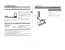
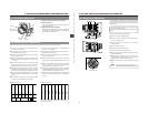
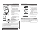
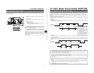
Viewfinder Status 1 Mode
Audio leve
ACCU -FOCUS
G
F
I
F5.6
STBY 4V21.<60
B
SD
CH1 ----+--
CH2 ----+--
M909
–38 –32 –26 –20 –14 –8 –2dB
6-8 Recording Level Adjustment
For each audio channel, use the AUDIO SELECT switches to
select whether the recording level adjustment should be set to
AUTO mode or MANUAL mode.
• When set to AUTO: Recording level is fixed. In this mode,
the recording level control does not
function.
•
When set to MANUAL:
Recording level can be adjusted
using the recording level controls for
each audio input.
Ⅲ Adjusting the recording level control of the front section
The recording level control on the front section only affects
the CH-1 channel sound.
To use the recording level control on the front section, make
the following settings.
• Set the CH-1 AUDIO SELECT switch to MANUAL.
• Set the VCR Setup Menu item No. 246 FRONT VOLUME
ENABLE to "ENABLE".
The recording level controls on the side section work
regardless of the setting of the VCR Setup Menu item No.
246 FRONT VOLUME ENABLE. ☞ See page 68.
Manual Adjustment of Recording Level
The recording level can be adjusted manually when the GY-
DV500 is in the record, record-pause or stop mode.
1.
Set the AUDIO SELECT switch of the channel whose
recording level that you want to adjust manually to MANUAL.
2.
Rotate the recording level control corresponding to the audio
input to be adjusted.
• Adjust so that the peak level does not exceed the -3dB
point when a loud sound is input.
• With microphone input, since the limiter circuit is activated,
the recording level will not exceed 0 dB even if the
recording level control is turned up.
CAUTION:
When the AUDIO INPUT LINE/MIC switch on the rear
section is set to MIC, be sure to check that the microphone
is connected to the AUDIO INPUT connector. If the
microphone is not connected, increasing the recording level
could cause noise from the input connector to be recorded
on the tape. When the microphone is not connected to the
AUDIO INPUT connector on the rear panel, set the LINE/
MIC switch to LINE or turn down the recording level control.
LIGHT
ON
OFF
COUNTER
CTL
TC
UB
RESET
OPERATE/WARNING
MONITOR
SELECT
STATUSSHUTTER
MENU
FILTER
1 3200k
2 5600k
3 5600k+ND
POWER
NG
G
A
IN
O
U
T
P
U
T
W
H
T
.B
A
L
V
T
R
ON OFF
ALARM
MONITOR
CH-1
CH-2
AUDIO
LEVEL
AUTO IRIS LOLUX
BACK L
NORMAL
SPOT L
STRETCH
NORMAL
COMPRESS
FULL AUTO BLACK
H
M
L
SAVE STBY
BARS CAM
ON
OFF
A
U
T
O
K
N
E
E
P
R
S
T
A
B
AUTO
WHITE
SKIN
AREA
ACCU
FOCUS
TAKE
VTR
ZEBRA
AUDIO
LEVEL CH-1
ON
OFF
VF
CH-1
CH-2
AUDIO
LEVEL
CH-1 CH-2
AUTO
MANUAL
FRONT
REAR
AUDIO SELECT
AUDIO INPUT
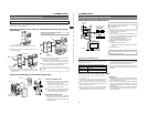
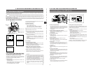
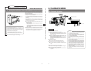
CH-1 recording level control
CH-2 recording level control
CH-1 recording level control
E
REV FWD
FBATT
H
HM
MSF
REMAIN
AUD LOCK
32k
CH 1
CH 2
48k
PB NDF
AUTO OFF DEW
L iRFSERVO
HOLD
SP
MENU
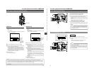
OVER
OVER
40 30 20 10 0
dB
Level meter
CH-2 Audio
select switch
CH-1 Audio
select switch
Ⅲ How to use the recording level control on
the front section
1 Set the recording level control on the front section to
maximum (10) position.
2 Initially, adjust the recording level using the CH1 recording
level control on the side.
3 When a loud sound is input during recording, use the
recording level control on the front section to lower the
recording level.
CAUTION:
Indicator level (reference)