


Chapter 2 Locations and Functions of Parts and Controls 2-35
2
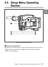
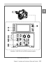
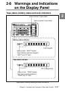
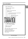
1 Tally indicator
Setting the TALLY switch to HIGH or LOW activates this indicator. The
indicator lights during recording on the VTR. It also provides the same
information as the REC indicator in the viewfinder: it comes on during
recording and flashes to indicate a problem.
2 TALLY switch
This switch controls the tally indicator, setting its brightness (HIGH or
LOW) or turning it off.
3 DIAG button
When the VTR section is in the stop mode, pressing this button puts the
camcorder into the self-diagnostic mode to test the display panel, camera
and VTR sections and give the test results.
Pressing this button again puts the camcorder back into the normal mode.
Refer to the Maintenance Manual for more information.
Caution
Do not press the DIAG button when the RM-P9 Remote Control Unit is
connected. Pressing the button with the RM-P9 connected will disturb
both the self-diagnostic and remote control functions. The only remedy
for this disturbance is to disconnect the RM-P9 and turn off the
camcorder POWER switch for a while.
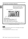
4 Back tally indicator
This indicator functions exactly the same way as the front tally indicator
when the back tally switch is set to ON.
5 Back tally switch
This switch turns the back tally indicator on and off.