


4-22
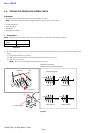
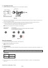
SAL35F14G (1.4/35G) (35mm F1.4G)
1000 mm collimator
Checking lens
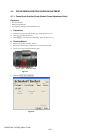
2. Frange Back (f’F) Check
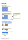
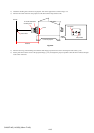
1) Attach the checking lens to the flange back tester, and set the 1000 mm collimator.
Fig.4-4-3
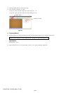
2) Set the focus ring of the checking lens to infinity end position while looking through the microscope, and align the optical axis to the
center of the chart image accurately.
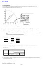
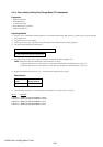
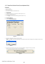
3) Turn the focusing knob of the tester until the chart image is the sharpest (red and green color areas are equal on the chart *).
*: Position in which the color of collimator chart changes from green into red and come into focus.
Also check the optical axis aligns with the chart center. (Refer to Fig.4-4-4.)
Note: Figure shows example. The cause depends on individual lens.
Fig.4-4-4
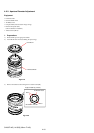
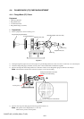
Optical Axis Adjustment
1) Turn the G10, or do the adjustment of looseness. After align the axis.
2) Apply the adhesive bond (B-10) to the G10 retainer.
Note: Tolerance: 0.02 mm or less
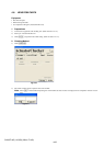
3. Checking Method
1) Calculate the flange back (f’F) of the checking lens using the following formula, and check that the specification of the Table 4-4-1 is
satisfied.
Flange back (f’F) of the checking lens = (SR flange back gauge) + (Number of short-pointer revolution) + (Reading of long-pointer)
Specification
Focal-length f’F (mm)
f (mm) (Infinity position)
35 44.58 to 44.60
Table 4-4-1
2) When the flange back (f’F) of the checking lens is out of specification of the Table 4-4-1, perform “4-4-2. Flange Back (f’F)
Adjustment”.
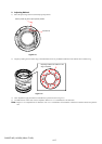
Optical Alignment
Best alignment
Incorrect aligned
e.g. As the focusing knob is turned, the chart may appear blurry as illustrated.
The cause depends on individual lens.