


2-5
Cisco Video Surveillance 5010/5011 Indoor Fixed HD IP Dome Camera User Guide
OL-22669-02
Chapter 2 Installation
Surface Installation
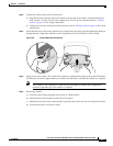
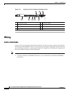
Step 3 Connect the wiring to the side of the back box:
a. Plug the network cable into the RJ-45 connector on the side of the camera. If the network has no
PoE, connect a 24 VAC Class 2 power supply to the 24 VAC power connector. Refer to
“Wiring”
section on page 2-10 for wiring connections.
b. Connect the necessary wiring for alarms and relays (refer to “Wiring” section on page 2-10 for more
information).
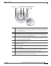
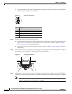
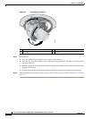
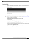
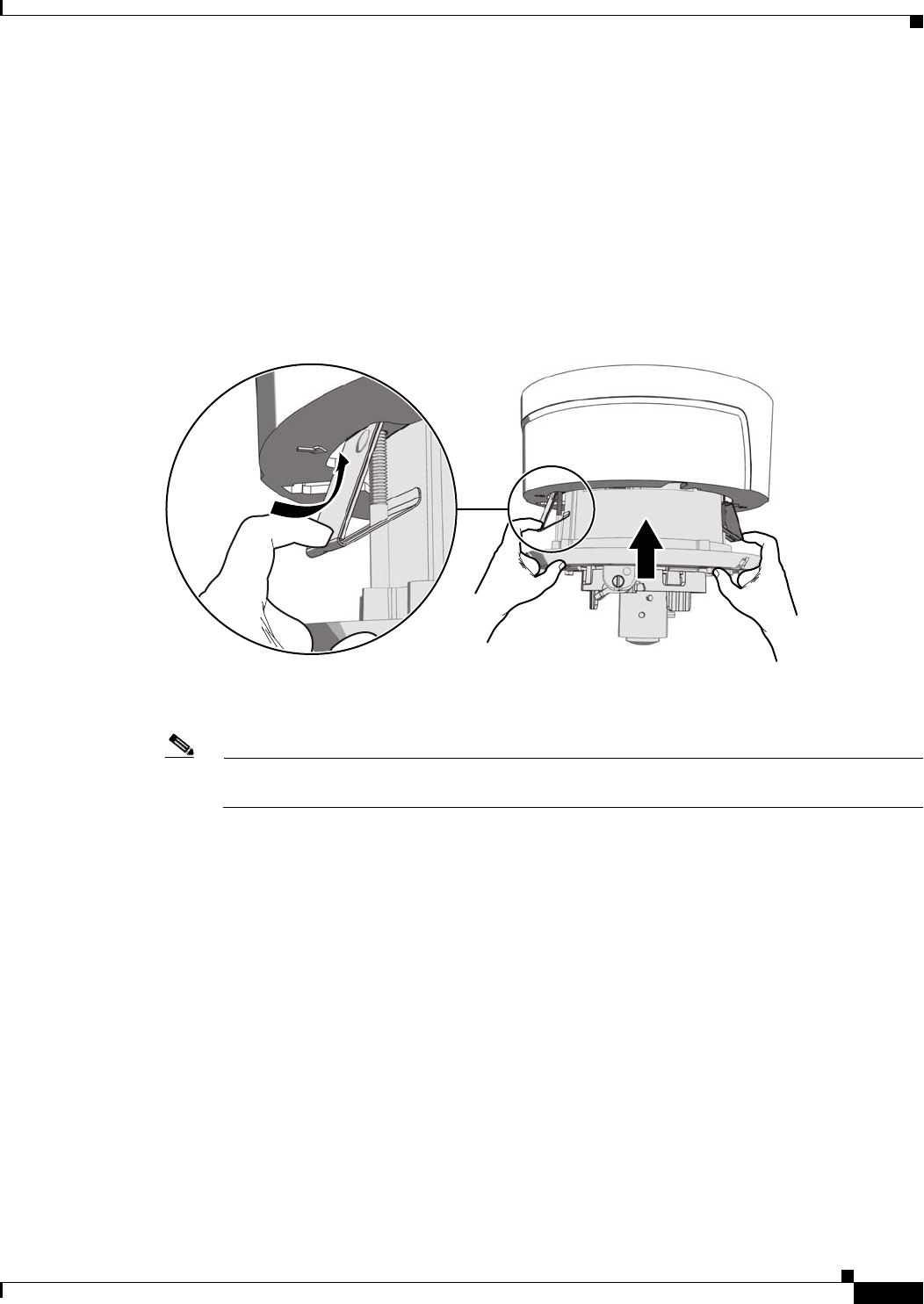
Step 4 Install the back box in the surface mount ring by compressing the spring clips and pushing the back box
through the hole. Tighten the machine screws completely to secure the back box to the ceiling.
Figure 2-5 Surface Back Box Installation
Step 5 Apply power to the camera. The camera will complete a configuration sequence; the green LED flashes
five times per second for approximately two minutes and then turns solid after the sequence is complete.
Note If the camera is not connected to a DHCP server and DHCP is enabled, the configuration
sequence might take up to five minutes to complete.
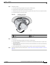
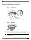
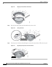
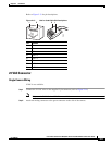
Step 6 Position the camera:
a. View the camera image using the service jack or a Web browser.
b. Unlock the tab locks located on each side of the camera.
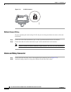
c. Manually rotate and tilt the camera module to position the camera. Do not over-rotate the module.
d. Lock the tab locks to secure the camera.
279050