


2-13
Cisco Video Surveillance 5010/5011 Indoor Fixed HD IP Dome Camera User Guide
OL-22669-02
Chapter 2 Installation
Wiring
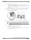
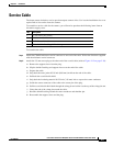
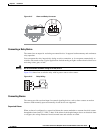
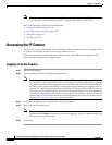
Figure 2-15 Alarm and Relay Connector
Connecting a Relay Device
The camera has an output for activating an external device. It supports both momentary and continuous
relay operation.
You can operate the relay interactively during an active connection, or it can operate automatically to
coincide with certain events. Typical applications include turning on lights or other electrical devices or
activating a door, gate, or lock.
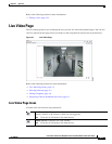
Warning
Do not exceed the maximum rating of 12 VDC, 0.15 A.
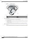
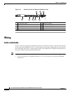
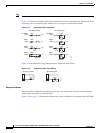
Figure 2-16 shows how to wire the relay with its power source to the camera.
Figure 2-16 Relay Wiring
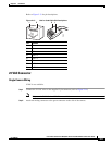
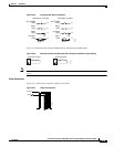
Connecting Alarms
The camera provides an alarm input for external signaling devices, such as door contacts or motion
detectors. Both normally open and normally closed devices are supported.
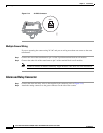
Supervised Alarms
When an alarm is configured as a supervised alarm, the camera maintains a constant electrical current
through the alarm circuit (3.3 VDC, 1 ohm). If the alarm circuit length changes, due to an electrical short
or a bypass, the voltage fluctuates from its normal state and activates an alarm.
RELAY
R1
ALARM
A1
2790893
12 VDC, 150 mA MAX
R1
A1
279049