


2-11
Cisco Video Surveillance 5010/5011 Indoor Fixed HD IP Dome Camera User Guide
OL-22669-02
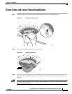
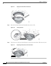
Chapter 2 Installation
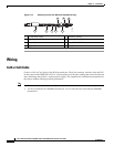
Wiring
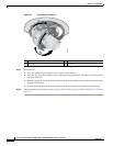
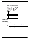
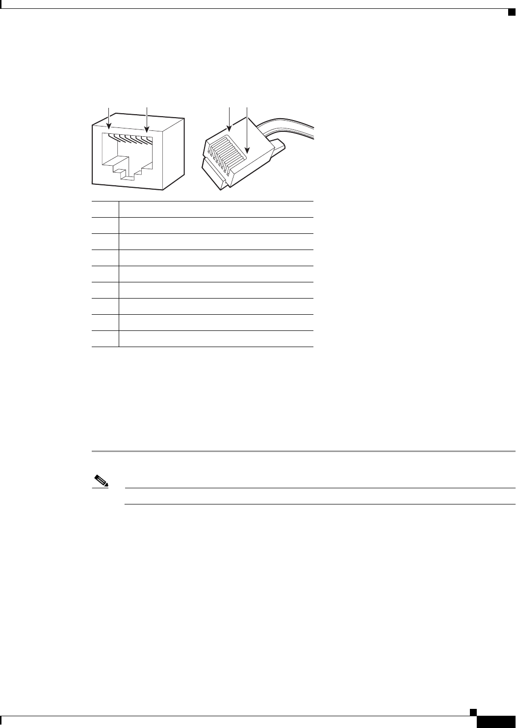
Refer to Figure 2-13 for pin descriptions.
Figure 2-13 Cat5 or Cat6 Cable Pin Descriptions
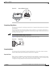
24 VAC Connector
Single Camera Wiring
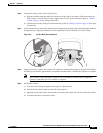
If PoE is not available:
Step 1 Connect the 24 VAC wires to the supplied 2-pin connector (refer to Figure 2-14).
Note Only use the 24 VAC wires if PoE is not available.
Step 2 Attach the mating connector to the green connector on the side of the camera.
Pin Function
1 TX+
2 TX–
3 RX+
4 PoE 1-2
5 PoE 1-2
6 RX–
7 PoE 3-4
8 PoE 3-4
1
2
3
4
5
6
7
8
1
2
3
4
5
6
7
8
1
8 8 1
279057