


ioxadm(8)
System Administration 67
Displays a summary of an External I/O Expansion Unit or link card’s
environmental state.
■ -e
Displays electrical states: measured voltage, current, fan speed, switch
settings.
■ -l
Displays LED states.
■ -t
Displays thermal readings.
If no target is specified, env displays a list of all sensors for all External I/O
Expansion Units.
If target specifies a box_id, env displays a list of sensor readings for all frus in
the specified External I/O Expansion Unit and the attached downlink cards.
If target is in the form of box_id followed by fru, then only environmentals
from that FRU will be printed. If an optional value for sensors is specified,
then only those types of sensors are displayed. These options may be used
concurrently.
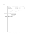
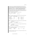
If target is in the form of a host path, only the downlink card information is
displayed. See
EXAMPLE 2.
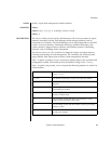
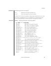
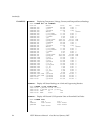
The results are listed in tabular format. Each FRU sensor is listed in the first
column. In the next column is the sensor name, such as T_AMBIENT for
ambient temperature, or V_12V_0V for the voltage reading of the 12V rail.
The third, fourth, and fifth columns display the sensor reading (Value),
sensor resolution (Res), and Units, respectively. See
EXAMPLE 1.
Each FRU can have a variety of different sensors. When specifying multiple
values for sensors, use spaces to separate the values. Possible values for
sensors can be seen in the Sensor column of
EXAMPLE 1. Units are given in
Celsius degrees, Volts, Amperes, SWITCH and RPM.
The sensors names are FRU-dependent and may change from FRU type to
FRU type and even among individual FRUs.
If the -v option is set, verbose output is displayed. In addition to the regular
output, the output also includes: the maximum and minimum values
supported by the sensors (Max and Min), along with the low and high
warning thresholds (Min Alarm and Max Alarm).
LED indicators do not support these fields.
(cont’d)