


Installing the SDI Video Matrix Switcher
15
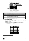
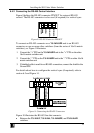
6.4.2 Connecting the RS-485 Control Interface
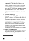
Figure 8 defines the RS-485 connector PINOUT for external RS-485
control. The RS-485 connector is also used (if required) for vertical sync:
Figure 8: RS-485 Connector PINOUT
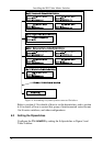
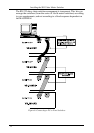
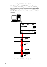
To connect an RS-485 connector on a VS-1616SDI unit to an RS-485
connector on one or more other switchers (from the series of 16x16 matrix
switchers), as Figure 9 illustrates:
1. Connect the “+” PIN on the VS-1616SDI unit to the “+” PIN on the other
16x16 matrix switcher unit
2. Connect the “-” PIN on the VS-1616SDI unit to the “-” PIN on other 16x16
matrix switcher unit
3. If shielded cable is used for an RS-485 connection, connect the shield to the
Ground PIN.
For details about how to configure the vertical sync (if required), refer to
section 6.5 and Figure 14.
Figure 9: Connecting the RS-485 Connectors
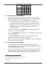
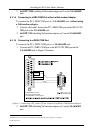
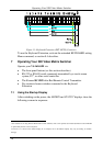
Figure 10 illustrates the RS-485 line that connects:
Between the VS-1616V, VS-1616A, VS-1616SDI, and VS-1616AD
switchers