


KRAMER: SIMPLE CREATIVE TECHNOLOGY
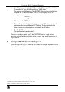
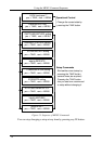
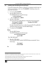
Using the MENU Command Sequence
32
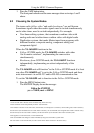
8.3.1 Understanding the SWITCHING METHOD Settings
Setting the VS-1616SDI unit as a Stand-Alone UNIT provides a choice of 4
SWITCHING METHOD settings:
NoVIS - switching occurs immediately after completion of front
panel or dry-contact operation or immediately after receiving an
RS-232 or RS-485 command, or an IR command. The switching
is independent of the vertical reference
EXTERNAL SYNC ANALOG - switching occurs during the
vertical interval of the video reference signal connected to the
ANALOG connector (this signal should be properly terminated
via the 75 (Term) button
1
)
EXTERNAL SYNC DIGITAL - switching occurs during the
vertical interval of the video reference signal connected to the
DIGITAL connector
INT# 1 DIGITAL - switching occurs during the vertical interval
of the video signal connected to Input # 1
Before choosing the EXTERNAL SYNC DIGITAL or the INT# 1
DIGITAL SWITCHING METHOD setting, it is necessary to install a
digital Genlock input board
2
. Without installing the optional digital Genlock
input board, these SWITCHING METHOD setting commands will be
unavailable.
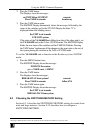
Setting the VS-1616SDI unit as a Large Matrix (instead of as a Stand-Alone
UNIT) provides a choice of 5 SWITCHING METHOD settings:
NoVIS, EXTERNAL SYNC ANALOG, EXTERNAL SYNC
DIGITAL, INT# 1 DIGITAL, (as described above)
MTX (SYNC from Matrix) - the vertical interval of the video
reference (selected on one unit in the Large Matrix system) is
present on the “SYNC” RS-485 terminal block connector
3
. This
reference signal applies to all switchers in the multi- switcher
system and facilitates switching all VS-1616SDI units
simultaneously
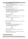
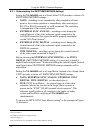
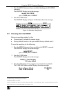
To choose the MTX (SYNC from Matrix) setting
4
as the example in Figure
14 illustrates:
1 Item 4 in Figure 2
2 Available for purchase as an optional extra
3 Item 6 in Figure 2
4 This sets the matrix sync configuration from another (Master) machine