


Your SDI Video Matrix Switcher
5
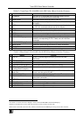
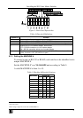
Table 2: Front Panel VS-1616SDI 16x16 SDI Video Matrix Switcher Features
# Feature Function
1 IR Receiver The red LED is illuminated when receiving signals from the
Kramer Infra-red remote control transmitter
2 Power Switch Illuminated switch supplying power to the unit
3 ALL Button Pressing ALL followed by an INPUT button, connects that input to
all outputs
4 OFF Button An OFF-OUT combination disconnects that output from the inputs;
an OFF-ALL combination disconnects all the outputs
5 IN Buttons Select the input to switch to the output
6 OUT Buttons Select the output to which the input is switched
7 STO Button Stores the current setting in the non-volatile memory
8 RCL Button Recalls a setup from the non-volatile memory
9 LCD MATRIX Display
1
Displays the selected input(s) switched to the output(s) (above or
below the corresponding OUTPUT label) and user interface
messages
10
LCD STATUS Display
1
Displays the matrix status (input to output connections)
11
MENU Button Selects the programming commands to setup the switcher
12
TAKE LED Shows the current TAKE button mode
13
TAKE Button Used to confirm and complete setup and switching
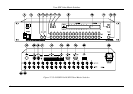
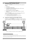
Table 3: Rear Panel VS-1616SDI 16x16 SDI Video Matrix Switcher Features
# Feature Function
14
DIGITAL Space for optional digital Genlock input board with BNC
Connector
15
EXT. SYNC BNC Connector Connects to the external sync source
16
ANALOG BNC Connector Connects to the analog Genlock source
17
75
Analog Genlock Button Press to terminate at 75 or release for looping
2
18
EXT. (extension) KEYS
Terminal Block Connectors
Connects to an external keyboard (remote unit)
19
RS-485 Detachable Terminal
Block Port
Pins # 1 and # 2 are for vertical sync and Ground connection, and
Pins # 3 and # 4 are for RS 485
20
RS-232 IN DB 9F Port Connects to the PC or the Remote Controller
3
21
RS-232 OUT DB 9M Port Connects to the RS-232 IN DB 9F port of the next unit in the
daisy-chain connection
22
SETUP Dipswitches Dipswitches for setup of the unit
23
Power Connector with Fuse AC connector enabling power supply to the unit
24
INPUTS BNC Connectors Connect to the digital video sources
25
OUTPUTS BNC Connectors Connect to the digital video acceptors
1 In sections 7.2.4 and 8, the word “Displays” refers to the LCD MATRIX and STATUS Displays
2 Push in to terminate the sync line. Push out when the sync line extends to another unit
3 If the unit is not the first unit in the line, connects to the RS-232 OUT DB 9F port of the previous unit in the line