


Contents
iii
Figures
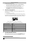
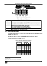
Figure 1: Default Dipswitch Setup on a Single Machine 3
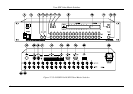
Figure 2: VS-1616SDI 16x16 SDI Video Matrix Switcher 4
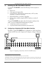
Figure 3: Configuring a Stand Alone 16x16 VS-1616SDI Switcher 6
Figure 4: Assembling a System of Interconnected Switchers 8
Figure 5: Rear Panel Dipswitches 9
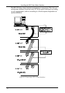
Figure 6: Connecting a PC to Four Switchers 12
Figure 7: Connecting a PC (with a 25-pin connector) without a Null-modem Adapter 14
Figure 8: RS-485 Connector PINOUT 15
Figure 9: Connecting the RS-485 Connectors 15
Figure 10: An RS-485 Control Interface Setup 16
Figure 11: Keyboard Extension (EXT. KEYS) Connector 18
Figure 12: Default Startup Status Display Sequence 19
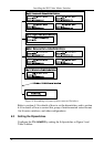
Figure 13: Sequence of MENU Commands 28
Figure 14: Choosing the MTX (SYNC from Matrix) Setting 33
Figure 15: Choosing what to INDICATE 35
Figure 16: Machine Identification 39
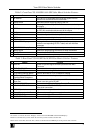
Tables
Table 1: Quick Reference Operating Guide for a Single Machine 3
Table 2: Front Panel VS-1616SDI 16x16 SDI Video Matrix Switcher Features 5
Table 3: Rear Panel VS-1616SDI 16x16 SDI Video Matrix Switcher Features 5
Table 4: Dipswitch Definitions 9
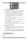
Table 5: Machine # Dipswitch Settings 9
Table 6: Summary of Basic RC-IR2 Setups 37
Table 7: Summary of Basic RC-IR2 Operations 38
Table 8: Technical Specifications of the VS-1616SDI Video Matrix Switcher 43
Table 9: Hex Table for the VS-1616SDI Video Matrix Switcher 44