


10
HDR 24/96
HDR 24/96
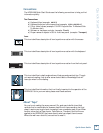
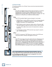
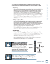
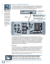
Sync Card & Cable - Word Clock and Digital Synchronization
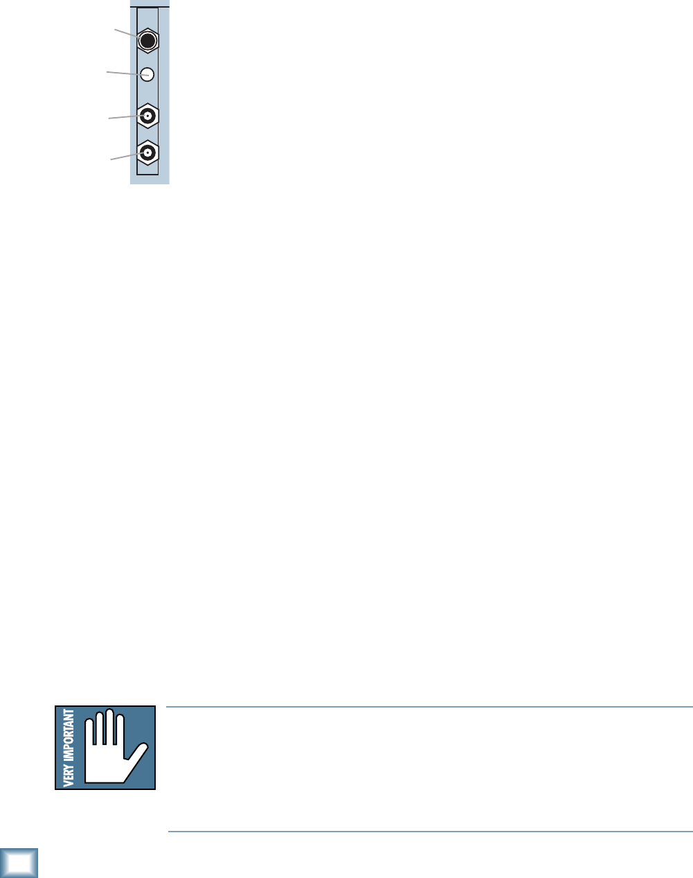
The Sync Card provides ports to synchronize the HDR24/96’s sample clock and
time/transport position to other equipment. The functions of the jacks and switch,
from top to bottom are:
• SMPTE Input / Output – This 1/4” TRS jack serves as an input when
slaved to incoming SMPTE time code, and as an output when generating
SMPTE time code to synchronize other devices with the HDR24/96.
• Termination Switch – This pushbutton switch selects the termination
impedance of the Word Clock / Video Input jack. When the switch is out,
the impedance is 10kΩ (bridging); when in, the impedance is 75Ω
(terminated).
• Word Clock / Video Input – This BNC jack receives either word clock,
composite video, or video blackburst as determined by the HDR24/96
Sample Clock source setting. Use this input when the HDR24/96 is
operating as a word clock slave.
• Word Clock Output - This BNC jack transmits word clock to other devices
in the system when the HDR24/96 is configured as the clock master.
Whenever digital audio devices are interconnected, the sample clock of every
device must run at exactly the same rate. This is usually accomplished by
selecting one device as the “master” clock source and distributing its word clock
signal to all the “slave” devices in the system. The master is configured to run
from its internal clock, and the slaves from external word clock. Some digital
interfaces are self-clocking (such as the AES input on many DAT machines) and
do not require a separate work clock connection. Others simply cannot be
configured as slaves. The master/slave designation must be correctly made for
each device to avoid the clicks and pops associated with asynchronous clocks.
SMPTE time code is used for time synchronization between the HDR24/96 and
other devices such as a video cassette recorder or another audio recorder. Connect
the jack to a time code input if the HDR24/96 is the master, or to a time code
source if the HDR24/96 is to be the time code slave.
Generally it doesn’t matter which device in a system serves as the word clock
master, except when synchronizing to time code or video. For example, if your
HDR24/96 Inputs and Outputs are connected to the Tape Inputs and Outputs of a
Mackie Digital 8
•Bus console using TDIF, either the HDR24/96 or D8B can be the
word clock master. However, if you later synchronize the HDR24/96 to time code
from a VTR, you must lock the VTR and HDR24/96 to a master video sync source
and lock the D8B (which can’t sync to video) to the word clock from the HDR24/
96. In this case the HDR24/96 is both a video slave and a word clock master. For
more detailed information on setups involving video and time code
synchronization, see the Applications Manual.
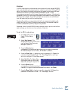
SYNC
SMPTE Input/
Output
Termination
Switch
Word Clock/
Video Input
Word Clock
Output
Note: Note:
Note: Note:
Note: For audio-for-video applications, the HDR24/96 can lock its word clock to
a video signal. In this configuration, there must be only one word clock depen-
dent device (the HDR24/96) locked to the video source. The HDR24/96 then
becomes the word clock master for the other digital devices in the system (for
example, a digital mixing console). Do not attempt to lock multiple digital de-
vices to the video signal, or you’ll get clicks.