


21
Quick Start Guide
Quick Start Guide
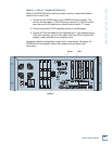
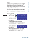
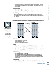
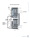
This example describes the hookup for the D8B console equipped for analog I/O.
TAPE IN/OUTS
INPUT OUTPUT
INPUT OUTPUT
INPUT OUTPUT
ANALOG I/O ANALOG I/O ANALOG I/O
TAPE IN/OUTS
INPUT OUTPUT
INPUT OUTPUT
INPUT OUTPUT
ANALOG I/O ANALOG I/O ANALOG I/O
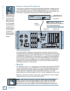
(6) DB25 to
DB25 Analog
Snakes
Digital 8•Bus
HDR 24/96
AIO•8 Cards
AIO•8 Cards
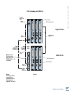
Cables & Hardware
(3) AIO•8 cards for HDR24/96
(3) AIO•8 cards for D8B
(6) DB25 to DB25 analog snakes
Hookup
1. Connect three snakes between the HDR24/96 Inputs (bottom connector)
and the corresponding D8B Tape Outputs (top connector).
2. Connect three snakes between the HDR24/96 Outputs (top connector) and
the corresponding D8B Tape Inputs (bottom connector).
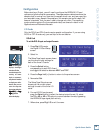
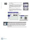
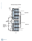
HDR24/96 Settings
1. Set the Sample Clock to Internal.
2. Set the Sample Rate and Bit Depth according to your preference. It is
not necessary to set the D8B and HDR24/96 to the same Sample Rate,
since with analog connections, the sample clocks on the two units are not
synchronized
Console Settings
1. Set the D8B Sample Clock to 44.1 k Internal or 48 k Internal according
to your preference.
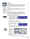
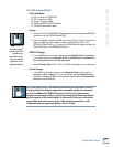
Note:Note:
Note:Note:
Note: Some older
AIO•8 cards have the
Input jack labeled as
“From Tape” and the
Output jack labeled
as “To Tape.” Other-
wise, they operate
identically. Sigh ...
long story.
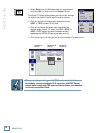
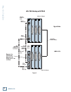
2. Connect three snakes to the HDR24/96 Outputs (top connector). Connect
the plug end of the snakes to the like-numbered Tape Return jacks on the
24•8 console.
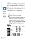
HDR24/96 Settings
1. Set the Sample Clock to Internal.
2. Set the Sample Rate and Bit Depth according to your preference.
Console Settings
Set the 24•8 console to the nominal +4 dBu operating level by setting the
five Operating Level switches in the Sub Out and Tape Return sections to the
‘out’ position.