RealPresence Collaboration Server (RMX) 1500/1800/2000/4000 Administrator’s Guide
Polycom®, Inc. 192
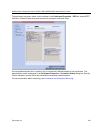
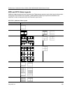
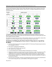
The following Telepresence Display Decision Matrix table below indicates how the speaker video will be
displayed on the various participant endpoints, when the MCU is managing Telepresence Room Switch
conference layouts.
For example, if the speaker’s endpoints has two screens and the participant’s endpoint only one, the
participant’s display is divided into two video layout cells with each video layout cell showing the input of one
of the speaker’s screens (endpoint).
If the participant endpoint has two screens, and the speaker endpoint only one, the speaker’s video will be
displayed on one of the participant’s screens, while the second screen remains black.
Guidelines for Managing the Room Switch Telepresence Layouts by
the MCU
● Only Room Switch layouts can be managed by the MCU. CP (Continuous Presence) layouts continue
to be managed by the MLA.
● Only CP-AVC conferences are supported.
● Lync Clients (with CSS add-in) are supported.
● SVC endpoints are not supported.
● It is recommended that the Speaker Change Threshold be set to 3 seconds.
● Telepresence endpoints are named using a text name followed by a number. For example, if an OTX
Telepresence room is named Oak, the three endpoint names would be Oak1, Oak2, and Oak3.
● Lecture mode is not supported in Telepresence Room Switch conferences managed by the MCU.
(This is because in Lecture mode, unlike Room Switch mode, the lecturer receives the CP layout of
conference participants.)
● Personal layouts are disabled. Therefore, any features that use personal layouts like Click&View can
not be used to change the layout, and Click&View DTMF digits will be ignored.


