


RealPresence Collaboration Server (RMX) 1500/1800/2000/4000 Administrator’s Guide
Polycom®, Inc. 270
● When creating a cascading link between two MGCs the MGCs must be configured to operate in VSW
mode.
For more details about the MGC to MGC connection, see the MGC Manager User’s Guide, Volume
II, Chapter 1, Ad Hoc Auto Cascading and Cascading Links.
● To enable the connection of the links between cascaded conferences, they must run at the same line
rate.
● To enable Content sharing between the RMX and the MGC, the rate allocated to the content must be
identical in both conferences. Make sure that the line rate set for both conferences, and the Content
Settings (Graphics, Hi-res Graphics or Live video) are selected correctly to ensure the compatible
rate allocation. For more details on the RMX rate allocation to the Content channel, see SIP BFCP
Content Capabilities.
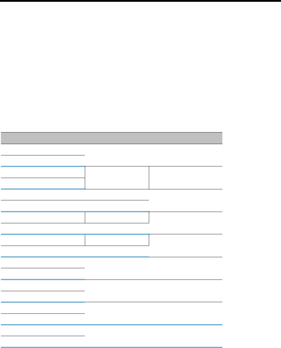
The following table summarizes Video Session Modes line rate options that need to be selected for each
conference in the cascading hierarchy according to the cascading topology:
* When MGC is on Level 3, Content cannot be shared between Level 2 and Level 3.
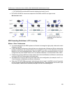
MIH Cascading – Video Session Mode and Line Rate
Topology MCU Type Video Session Type Line Rate
Level 1 RMX CP - HD 1.5Mb/s, 1Mb/s, 2Mb/s
Level 2 RMX
Level 1 RMX CP - CIF 768Kb/s, 2Mb/s
Level 2 RMX
Level 1 RMX CP 768Kb/s, 2Mb/s
Level 2 MGC CP or VSW
Level 1 MGC CP - CIF 263 768 kb/s, 2Mb/s
Level 2 RMX CP - CIF 264
Level 1 MGC VSW - HD 1.5Mb/s
Level 2 RMX VSW HD
Level 2 RMX CP - HD 1.5Mb/s, 1Mb/s, 2Mb/s
Level 3 RMX
Level 2 MGC VSW* 384 kbps, 768 kbps
Level 3 MGC
Level 2 RMX CP/VSW -HD 1.5Mb/s, 1Mb/s, 2Mb/s
Level 3 MCS 4000
Level 2 RMX CP - CIF 768kb/s, 2Mb/s
Level 3 MCS 4000