


Chapter 1 Overview
12 Chapter 1 Overview
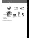
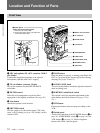
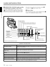
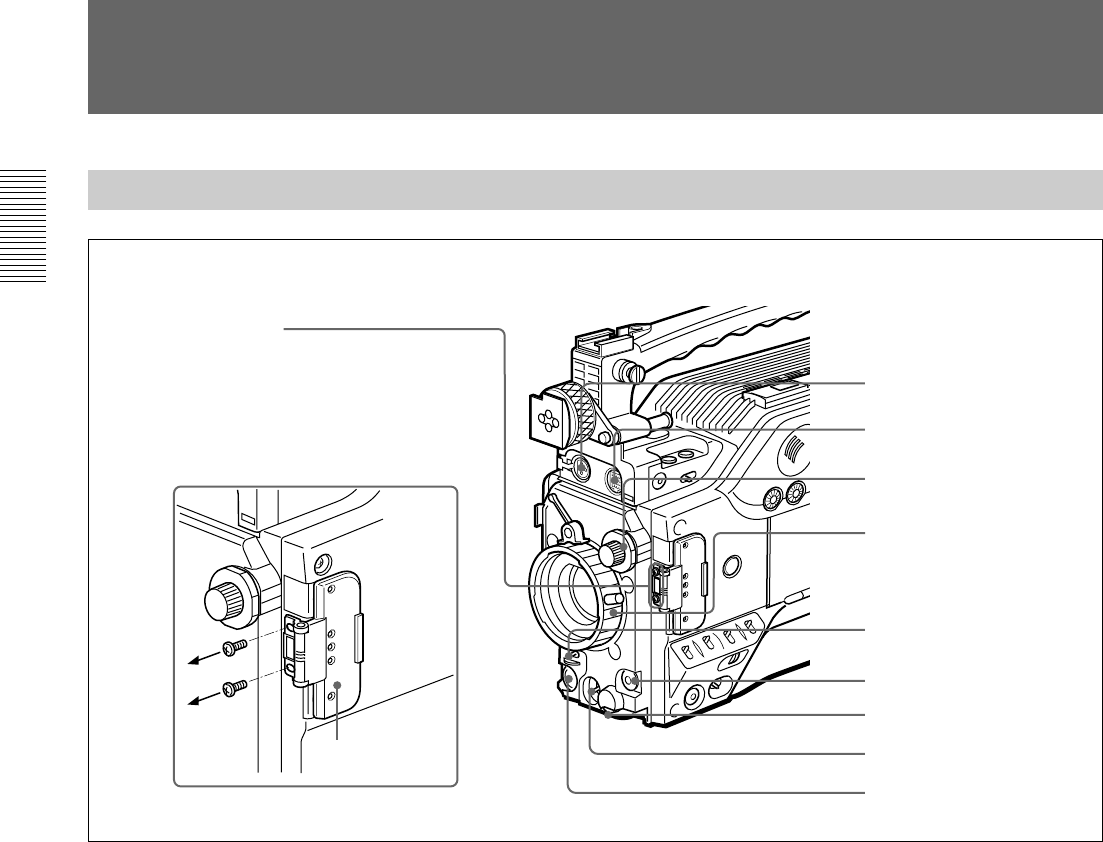
1 MIC IN +48 V connector
2 VF connector
3 FILTER control
4 Lens mount
5 SHUTTER switch
6 TAKE button
7 AUDIO LEVEL knob
8 WHT/BLK switch
9 VTR button
0 Switch guard
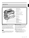
Front View
1 MIC (microphone) IN +48 V connector (XLR 3-
pin, female)
Connect the supplied microphone or an optional
microphone (operable with a 48 V supply).
2 VF (viewfinder) connector (20-pin)
This is the connector for the DXF-801/801CE
viewfinder.
3 FILTER control
Select the color temperature conversion filter
appropriate to the lighting conditions.(See page 49.)
4 Lens mount
Attach the optional zoom lens here.
5 SHUTTER switch
Use this switch to set the shutter speed, CLS (clear
scan), or EVS setting (see page 116).Usually, set this
switch to OFF.
6 TAKE button
Press this button to specify an editing point (Mark IN/
OUT or Cue point) at the current tape position during
shooting.(See pages 70 and 71.)
7 AUDIO LEVEL knob
You can use this knob to manually adjust the channel 1
audio recording level.
8 WHT/BLK (white/black) switch
This switch is used for automatic adjustment of the
white balance and black balance.(See pages 112 to
115.)
9 VTR button
Pressing this button starts and stops recording on the
VCR.
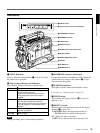
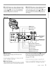
0 Switch guard
Avoids miss-operation of the EZ MODE button (4 on
page 14), A.IRIS MODE switch (6 on page 14), and
ATW button (qf on page 14). When using these
buttons and switch, open the guard.
Location and Function of Parts
How to remove the switch guard
1. Detach the two screws (M3).
2. Remove the switch guard, and replace the
screws detached in step 1.
Switch guard