


Chapter 1 Overview
Chapter 1 Overview 21
REC TIME SKIN DTL EXT VTR
OUTPUT
VTR
TRIGGER
AUDIO LEVEL
AUDIO SELECT
AUDIO IN
CH-1
LITHIUM BATT
MENU
TTL
DUR
ON
OFF
OFF
TTL RESET
PARALLEL
PRESET
DATE/TIME
F-RUN
REGEN
F-RUN
R-RUN
VJ MIC
WRR
SET
INT ONLY
EXT ONLY
FRONT
REAR
MIX
EXT
VBS
COMPONENT.
MONITOR SELECT
Y/C
SET
ClipLink
CONTINUE
ADVANCE SHIFT
CH-1
CH-2
FRONT MIC
LOW CUT
ON
OFF
MONITOR OUT
CHARACTER
ON
OFF
AUTO
MAN
CH-2
HYPER
GAIN
ON
OFF
SETUP
FILE
STD
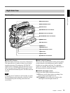
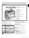
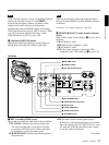
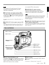
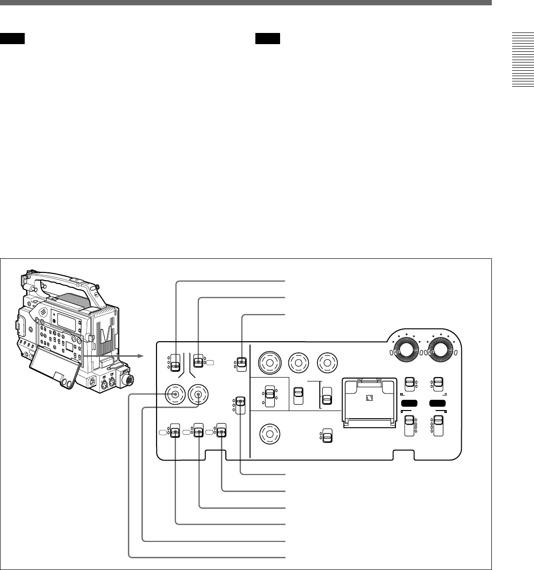
Left side
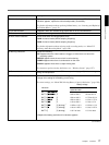
1 REC TIME switch
2 SKIN DTL switch
3 EXT VTR OUTPUT switch
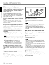
1 REC (recording) TIME switch
Selects the recording time indication in the viewfinder.
TTL (TOTAL): Displays the total recording time.
The total recording time is not reset even when
you stop the VCR and power off the camcorder,
for example, to replace the battery pack.
DUR (DURATION): Displays the recording time of
the current cut.
OFF: Switches off the recording time display.
If, however, in advanced menu page 6 you set the
time code display item (TC IND) to ON (see page
90), then the VCR time data (time code, counter,
or user bit value) is displayed.
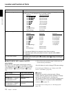
Note
If the ClipLink function is set to on (meaning ClipLink
shooting is allowed) in menu 211 and CONT is
displayed in the display window, regardless of the
setting of this switch, the time code generator
automatically enters the REGEN mode at recording.
(The ClipLink function is set to OFF at factory.) When
you will not perform ClipLink shooting, set the
ClipLink function to oFF (see page 109).
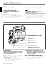
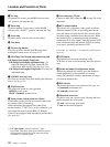
0 ClipLink CONTINUE button
When restart ClipLink shooting, press this button to
add the new clip at the end of the recorded clips.
Note
When restart recording without pressing this button,
the pre-recorded ClipLink log data and Index Pictures
are deleted.
For details , see “ClipLink Shooting” (page 68).
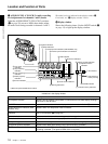
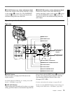
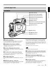
qa MONITOR SELECT (audio monitor selection)
switch
Selects audio output via the speaker (0 on page 18) or
earphone.
CH-1: Channel 1 audio
MIX: Mixed audio (channels 1 and 2)
CH-2: Channel 2 audio
EXT: The sound selected by an external VCR
connected to the VTR connector (0 on page 26)
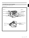
4 VTR TRIGGER switch
5 FRONT MIC LOW CUT switch
6 SETUP switch
7 HYPER GAIN switch
8 SKIN DTL SET button
9 TTL RESET button
(Continued)