


Chapter 1 Overview
26 Chapter 1 Overview
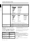
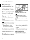
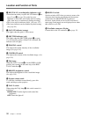
Location and Function of Parts
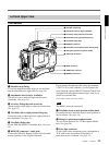
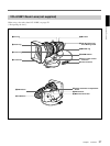
3 Battery attachment interface
Attach a battery pack or an AC-DN1/DN2A, AC
Adaptor.When using the WRR-855A synthesized tuner
(for wireless microphones), attach the CA-WR855
Camera Adaptor here.
For information about fitting a battery pack or an AC
adaptor, see “Power Supply” (page 46). For information
about attaching a synthesized tuner, see “Connecting to
Audio System” (page 39).
4 DC IN (DC power input) connector (XLR 4-pin,
male)
To use the camcorder with an AC power supply,
connect an optional AC-550/550CE or CMA-8A/
8ACE AC Adaptor.
5 AUDIO IN CH-1/CH-2 (audio input channel 1
and 2) connectors (XLR 3-pin, female) and input
selection switches
Connect a microphone or other external audio
equipment.Set the input selection switches as
shown below according to the microphone or
equipment.
MIC+48V ON (right position): For connecting to a
48-V microphone
Note
If this position is selected for a microphone other than
48-V microphone, the microphone may be damaged.
MIC (center position): For connecting any
microphone other than 48-V microphone
LINE (left position): For connecting an external
audio signal source such as a stereo amplifier.
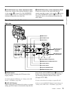
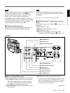
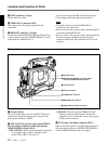
6 WRR (synthesized tuner) connector (7-pin)
Insert the WRR-855A synthesized tuner into the CA-
WR855 Camera Adaptor and connect the CA-WR855
here.
For information about attaching a synthesized tuner, see
“Connecting to Audio System” (page 39)
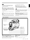
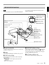
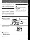
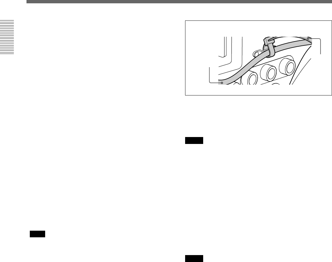
7 Cable clamp
Fasten an i.LINK cable (DV connecting cable) to the
clamp using the supplied binding tie so that the plug is
not pulled out.
8 DV OUT connector (6-pin)
Connect to the DV input connector of an external
VCR.
Notes
• This connector will not work as an input connector.
• When an external equipment, such as VCR, is
connected to this connector, the ClipLink and the
audio fade-in/fade-out function during recording will
not work.
9 DC OUT (DC power output) connector (4-pin,
female)
This connector supplies power for a WRR-810A/860A
UHF Portable Tuner.
0 VTR connector (26-pin, male)
Connect an external VCR.
Notes
• This connector always outputs the signals from the
camera. It is impossible to output the playback video
of the internal VCR.
• A camera control unit (CCU) cannot be connected to
this connector.
• The image size on the viewfinder or on the screen of
the RM-VJ1 will not switched automatically, even if
the aspect ratio (16:9/4:3) of the return signal, input
from an external VCR, is switched.
qa BREAKER (breaker reset) button
If an excessive current flows in the internal circuits,
the internal circuit breaker shuts off the power
supply.Push this button after eliminating the cause of
the excessive current.
Binding
tie
i.LINK
cable (DV
connecting
cable)