


Chapter 1 Overview
24 Chapter 1 Overview
Location and Function of Parts
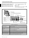
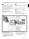
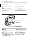
0 LENS connector (12-pin)
Connect the lens cable.
qa VIDEO OUT connector (BNC)
This outputs the video signal captured by the
camcorder.
qs REMOTE connector 2 (10-pin)
Connect the optional RM-M7G Remote Control Unit
to this connector. Set the CAMERA SELECT switch
on the bottom of RM-M7G to 1.
You can also connect the RM-VJ1 Remote Control
Unit (equipped with microphone and monitor.)
Notes
• EZ mode cannot be used if the RM-M7G is
connected to the camcorder.
• Be sure to turn off the power of the camcorder before
connecting the RM-M7G/VJ1.
• Be sure to turn off the power of the camcorder before
disconnecting the equipment connected to this
connector. Otherwise, the camcorder will not work
properly.
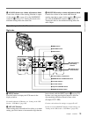
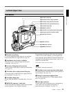
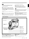
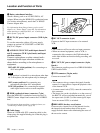
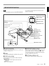
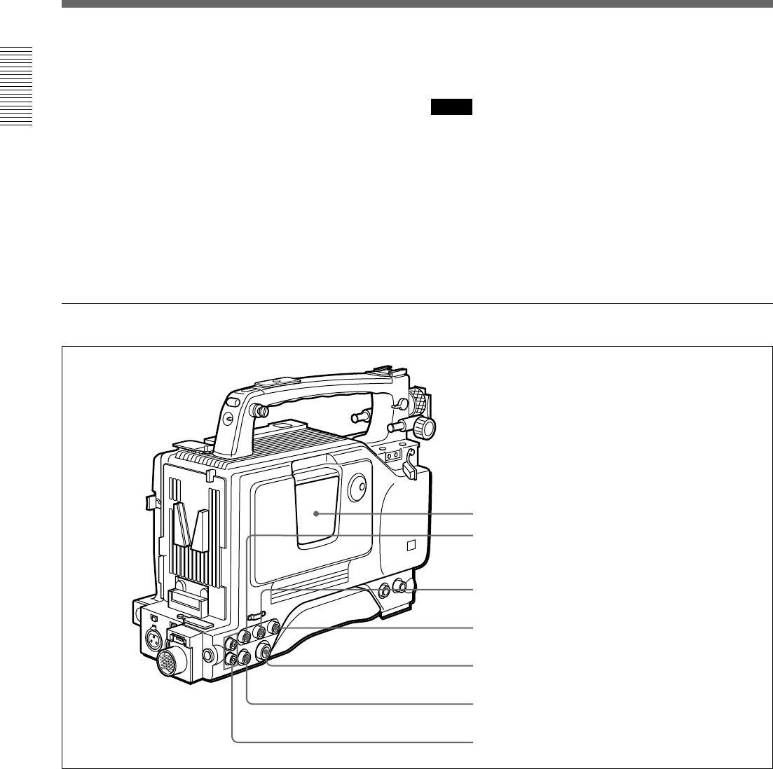
Rear section
1 Cassette holder
Power the camcorder and press the EJECT button to
open the lid. Insert the cassette and close the lid by
pressing the indication “PUSH”.
2 GEN LOCK IN (gen lock video input)/VIDEO
IN (video input) connector (When the optional
DSBK-501/501P is fitted) (BNC)
GEN LOCK IN: When synchronizing the camcorder
to an external signal, input a reference video
signal (VBS or BS). (See page 81.)
1 Cassette holder
VIDEO IN: When the optional DSBK-501/501P
Analog Composite Input Board is fitted to the
camcorder, you can input the analog video signals
(VBS) to this connector.
3 TC IN (time code input) connector (BNC)
Input an external signal for synchronizing the built-in
time code generator.Use an SMPTE (DSR-500WSL)
or EBU (DSR-500WSPL) time code signal.
2 GEN LOCK IN/VIDEO IN connector (When
the optional DSBK-501/501P is fitted)
3 TC IN connector
4 TC OUT connector
5 S VIDEO OUT connector
6 MONITOR OUT connector
7 AUDIO OUT CH-1/CH-2 connectors