


Chapter 1 Overview
30 Chapter 1 Overview
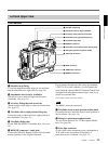
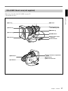
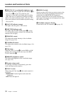
6 REC/TALLY (recording/tally) indicators (red)
• From the time when you press the VTR button (9 on
page 12 and qs on page 28) on the lens (not
supplied) or camcorder, this flashes until recording
starts, then stays on continuously during recording.
• This is also used to indicate a fault. (See page 127.)
• The lower indicator can be disabled by menu setting.
(See page 89.)
7 GAIN UP indicator (orange)
This lights when the gain is 3 dB or more.
8 SHUTTER indicator (red)
This lights when the SHUTTER switch (5 on page
12) is in the ON position. (If the EVS is selected, the
indicator will not light.)
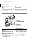
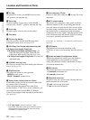
9 PEAKING control
This adjusts the outline intensity of the viewfinder
image. (See page 118.)
0 CONTRAST control
This adjusts the contrast of the viewfinder image. (See
page 118.)
qa Tally lamp
When the TALLY switch qf is in the HIGH or LOW
position, this operates in the same way as the REC/
TALLY indicators 6.
qs BRIGHT (brightness) control
This adjusts the brightness of the viewfinder image.
(See page 118.)
qd Eyepiece release catch
To view the viewfinder screen directly, press this
catch, and hinge up the eyepiece.
qf TALLY switch
When using the Tally lamp qa, this switch controls it
as follows.
HIGH/LOW: Turn the light on and control the
brightness.
OFF: Turns the light off.
Location and Function of Parts
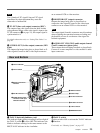
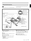
qg DISPLAY switch
Set this switch to OFF when you want to remove the
character data from the viewfinder and the monitor
connected to the MONITOR OUT connector.
However, items which are set to OFF in advanced
menu page 5 and page 6 are not displayed even when
this switch is set to ON.
qh Viewfinder connector (20-pin)
Connect this to the VF connector (
2
on page 12).