


Chapter 2 Fitting and Connections
42 Chapter 2 Fitting and Connections
Using Accessories
Using the RM-LG1 Remote Control Unit
You can control the camcorder using the supplied RM-LG1 Remote Control Unit.
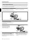
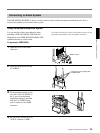
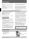
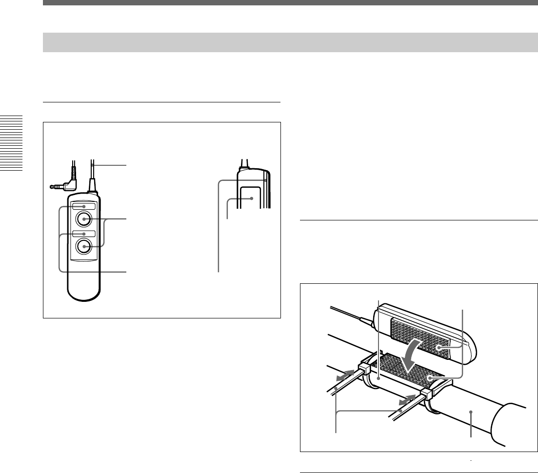
Location and Function of Parts
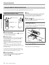
1 Cable with mini-plug
Connect to the REMOTE connector 1 (5 on page 23)
on the DSR-500WSL/500WSPL.
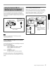
2 Switches 1 and 2
You can assign functions to these switches using the
advanced menu page 3 (see page 88) of the DSR-
500WSL/500WSPL.
Each can be used as the following types of switch:
VTR switch, MARK switch, CUE switch, or NG
switch.
At the shipping of the DSR-500WSL/500WSPL,
switch 1 is set as the VTR switch and switch 2 is set as
the MARK switch.
For information about the advanced menu and function of
each switch, see “Location and Function of Parts” on page
12 and “Viewfinder Advanced Menu” on page 86.
3 Switch name displays
Stickers (supplied with RM-LG1) can be attached here
to indicate which functions are assigned to the
switches 1 and 2 2.
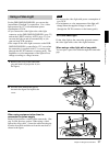
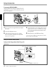
4 Velcro
When using the unit on the panning rod of the tripod,
this is used to attach the unit to the panning rod
mounting bracket (supplied with RM-LG1).
5 Cable clamp groove
When the cable 1 is passed underneath the unit, the
cable can be placed in this groove.
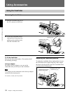
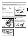
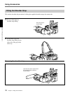
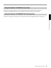
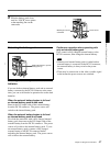
Attaching the RM-LG1
Use the binding ties and panning rod mounting bracket
to attach the unit to a panning rod.
Removing the RM-LG1
Lift up the tab to loosen the binding ties.
Velcro
Binding ties
1
2
1 Cable with mini-plug
2 Switches 1 and 2
3 Switch name
displays
4 Velcro
5 Cable clamp
groove
Panning rod mounting bracket
Panning rod