


Chapter 1 Overview
22 Chapter 1 Overview
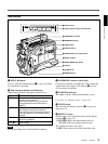
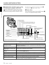
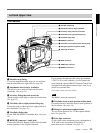
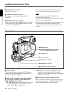
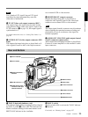
Location and Function of Parts
Note
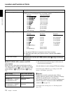
The recording time displayed when this switch is set to
TTL or DUR is obtained by counting the duration of
the internal reference signal input to the camcorder.
The value may not agree exactly with the value
derived from the time code values. Furthermore, the
value displayed may not be correct when another
manufacture’s VCR is connected to the camcorder.
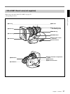
2 SKIN DTL (skin detail) switch
Set this switch ON to use the skin detail correction
function.
For details, see “Skin Detail Correction” (page 123).
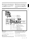
3 EXT VTR OUTPUT switch
Depending on the external VCR connected to the VTR
connector (0 on page 26), this switches the video
signal output to the VCR.
COMPONENT/VBS: Component/composite video
signal
Y/C: S-video signal
4 VTR TRIGGER switch
Sets the function of the VTR button on the camcorder
or lens when a VCR is connected to the VTR
connector (0 on page 26).
PARALLEL: Operates both internal and external
VCRs.
INT ONLY: Operates the internal VCR only.
External VCR operation is performed locally.
EXT ONLY: Operates the external VCR only.
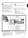
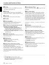
5 FRONT MIC LOW CUT switch
Set this switch to ON to insert a high-pass filter in the
microphone circuit, reducing wind noise.
Normally leave the switch in the OFF position.
6 SETUP switch
Use this switch to select the camcorder setup method.
FILE: Set up using setup files and the setup menu.
STD: Set up using the setup menu.Setup file data is
not displayed.
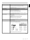
7 HYPER GAIN switch
Setting this switch to the ON position increases the
gain by a factor of about 60 or 120 with respect to 0
dB (a 30 or 36 dB increase by electronic amplification
and a 6 dB increase for DPR, bringing about a total
gain increase of 36 or 42 dB).
When this switch is in ON position, the indication
“HYPER” appears in the viewfinder, and the GAIN
UP indicator in the viewfinder also lights.
When finished shooting, return this switch to OFF
position. The HYPER indication disappears and the
GAIN UP indicator goes out.
Note
Increasing the gain with this switch reduces the
horizontal resolution by approx. 50%.
8 SKIN DTL (skin detail ) SET button
Press this button with the SKIN DTL switch 2 has
been set to ON to display the area detect cursor on
viewfinder screen. Place the cursor on the target and
press this button to perform skin detail correction.
For details, see “Skin Detail Correction” (page 123).
9 TTL (total) RESET button
Pressing this button resets the total recording time
(TTL selection) to 0.