178
Specifications
Appendix
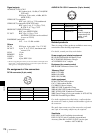
Signal outputs
AUDIO OUT CH-1/CH-2
RCA phono jack, –10 dBu, 47 k"%(PDW-
F330 only)
XLR type, 5-pin, male, +4 dBu, 600 "
(PDW-F350)
VIDEO OUT (composite)
BNC type 1.0 Vp-p, 75 ", unbalanced
VIDEO OUT (component, PDW-F330 only)
BNC type (1 set), Y: 1.0 Vp-p, 75 ",
R–Y/B–Y: 0.7 Vp-p, 75 "
HDSDI OUT (PDW-F350 only)
BNC type, SMPTE 292M
TC OUT BNC type, 1.0 Vp-p, 75 "
(On PDW-F330, this can be switched
to serve as TC IN)
EARPHONE (mini jack)
8 ", – ! to –15 dBs variable
Others
DC IN XLR type, 4-pin, male, 11 to 17 V DC
DC OUT 4-pin, 11 to 17 V DC, maximum rated
current 0.2 A
LENS 12-pin
REMOTE 8-pin
LIGHT
1)
2-pin
i.LINK 6-pin, IEEE 1394
1) The accessory fitting shoe which you can use to attach a video light to this
unit is of the
1
/
4
-inch tapped hole type. If you want to replace this with a
slide-type shoe, contact your Sony dealer.
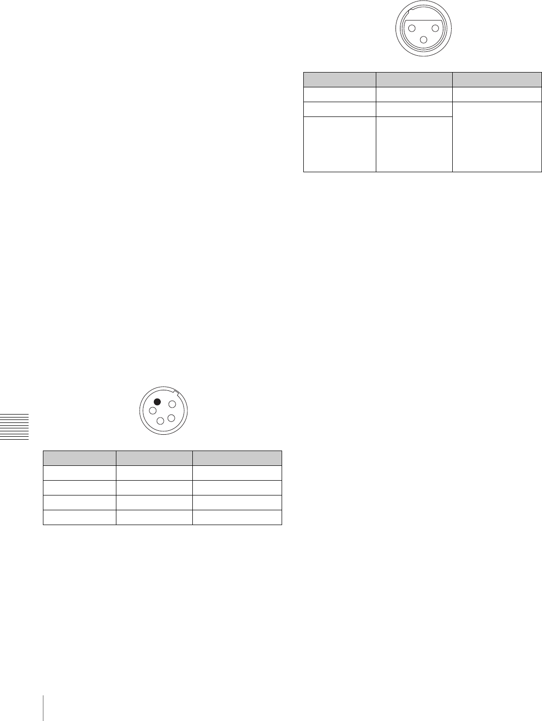
Pin assignment of the connectors
DC IN connector (4-pin, male)
AUDIO IN CH-1/CH-2 connector (3-pin, female)
Related products
There is a range of Sony products available to meet every
conceivable video shooting requirement.
For details, consult your Sony sales dealer.
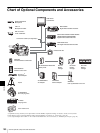
Power supply and related equipment
BP-GL95/GL65/L60S/L80S Battery Pack
BC-L70/M150/L500 Battery Charger
AC-DN2B/DN10 AC Adaptor
Equipment for remote control
RM-B150/B750 Remote Control Unit
“Memory Stick”
MSH-32 (32 MB)
MSH-64 (64 MB)
MSH-128 (128 MB)
Audio equipment
ECM-673/674/678 Microphone
CAC-12 Microphone Holder
CA-WR855 Camera Adaptor
WRR-855 UHF Synthesized Tuner
WRR-861/862 UHF Synthesized Tuner
WRT-822/824 UHF Synthesized Transmitter
WRR Tuner Fitting (service part number: A-8278-057-B)
DMX-P01 Portable Digital Mixer
For Audio equipment described above, confirm whether
the connector is male or female and the number of pins on
the connector.
The audio input connectors of the camcorder are female
and 3-pin. A converting adaptor may be required.
Viewfinder
DXF-20W 2-inch Viewfinder (monochrome)
DXF-51/51CE 5-inch Viewfinder (monochrome)
Accessory Shoe Kit for DXF-51/51CE (service part
number: A-8274-968-B)
Pin number Signal Standard
1 EXT DC IN (G) GND
2 – –
3 – –
4 EXT DC IN (X) +11 to +17 V DC
1
2
3
4
Pin number Signal Standard
1 AUDIO IN (G) GND
2 AUDIO IN (X)
–60 dBu, –50 dBu,
–40 dBu
When ZI is equal to
or more than 3 k
"/
+4 dBu, 10 k
",
balanced
3 AUDIO IN (Y)
3
2 1


