52
Connecting
Chapter 2 Preparations
For connections using FAM (file access mode), see “File
Operation” (page 155).
Settings required for an i.LINK connection
i.LINK MODE setting
Set the method of connection between this unit and an
external device. On the OUTPUT page of the
OPERATION menum, set i.LINK MODE to AV/C
(Audio/Video Control). (The factory default setting is AV/
C.)
Make the i.LINK AUDIO OUT setting depending on the
connected device (see the next item).
i.LINK AUDIO OUT setting
Set the audio output channels for the (i.LINK) DV OUT
S400 connector. On the AUDIO-2 page of the
MAINTENANCE menu, set i.LINK AUDIO OUT to one
of the following. (The factory default setting is “2CH”.)
2CH: Output channels 1 and 2 (16 bits, 48 ksps)
4CH: Output channels 1 to 4 (12 bits, 32 ksps)
When the scan mode is 23.98P, video, audio, or timecode
output via the i.LINK connection may not be continuous.
Using the camcorder as a feeder
To copy digitally from the camcorder to the VTR
without the editing function
Using an i.LINK cable (DV cable) to connect a digital
video cassette recorder with an i.LINK connector to the
camcorder, digital copy of video and audio can be carried
out.
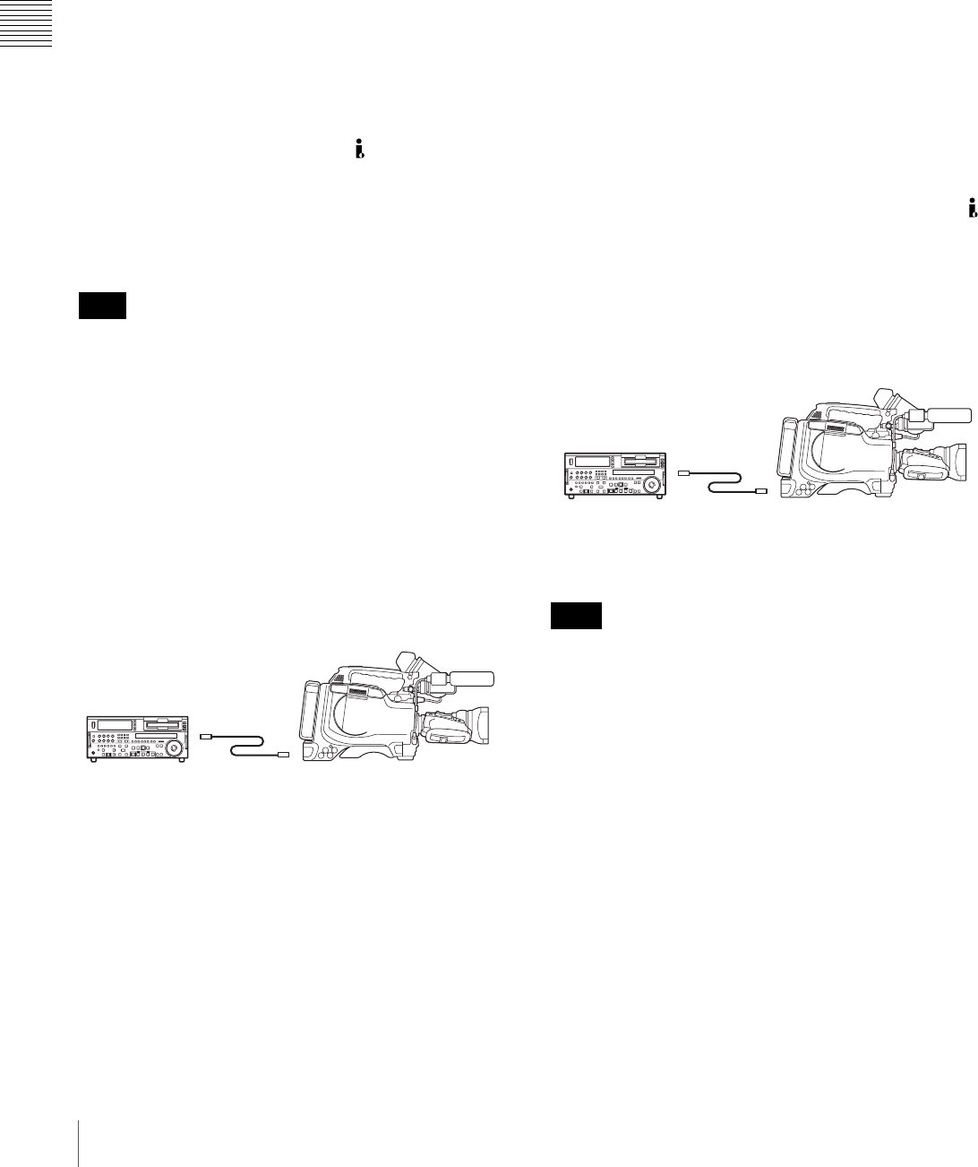
Example of connection
1
Make the following settings to prepare the external
VTR.
• Set REC MODE to the same recording mode as that
of the camcorder.
• In NTSC color system, when the recording mode is
set to DVCAM, select either DF or NDF.
• Set AUDIO MODE to either 4-channel or 2-channel
mode, according to the disc that is played on the
camcorder.
2
Pause recording on the external VTR.
3
Play the disc on the camcorder.
4
Check the playback on the camcorder, and when
playback reaches the scene that you want to record,
start recording again on the external VTR.
The copy to the external VTR starts.
5
When copy to the external VTR is finished, stop
playback of the disc on the camcorder.
For details about external VTR operations, see the
instruction manual supplied with the external VTR.
To control the camcorder from a VTR with editing
function
By connecting a VTR with an i.LINK connector to the
(i.LINK) DV OUT S400 connector of the camcorder using
an i.LINK cable (DV cable), you can control playback and
recording on the camcorder and perform cut editing and
digital copy.
Example of connection
When using the DSR-2000A/2000AP, press the i.LINK
button on the remote control setting section of the VTR.
To use the automatic copying function of the DSR-2000A/
2000AP, it is necessary to set the recording format of the
camcorder to DVCAM on the FORMAT page of the
OPERATION menu.
For details on the external VTR, see the instruction manual
supplied with the external VTR.
To control the camcorder from a nonlinear
editing system
Using the i.LINK cable (DV cable), you can transfer video
and audio signals to a nonlinear editing system from the
camcorder. Editing software that supports the selected
recording format (DVCAM) must be used.
Note
External VTR
DSR-1800A/1800AP/
45/45P, etc.
PDW-F330/F330P/F350/F350P
i.LINK cable
(DV cable)
Note
External VTR
PDW-F330/F330P/F350/F350P
DSR-2000A/2000AP, etc.
i.LINK cable
(DV cable)
