32
Location and Function of Parts
Chapter 1 Overview
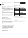
i 5600 indicator
Appears when the electric color temperature filter function
is on.
j Filter
Indicates the currently selected filter type.
k White balance memory
Indicates the currently selected white balance automatic
adjustment memory.
A: Displayed when the WHITE BAL switch is set to A.
B: Displayed when the WHITE BAL switch is set to B.
P: Displayed when the WHITE BAL switch is set to PRST
or when the preset button on an RM-B150 has been
pushed.
T: Displayed when ATW is being used.
l Gain value
Indicates the gain value (in dB) of the video amplifier, as
set by the GAIN switch.
m Shutter speed
Indicates the shutter speed or the shutter mode. However,
if the SHUTTER switch (see page 14) is set to OFF,
nothing is displayed.
For details of the displayed shutter speed, see “Setting the
Electronic Shutter” on page 62.
n Operation/alarm message display area
For details, see “Operation/alarm messages” on
page 166.
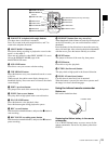
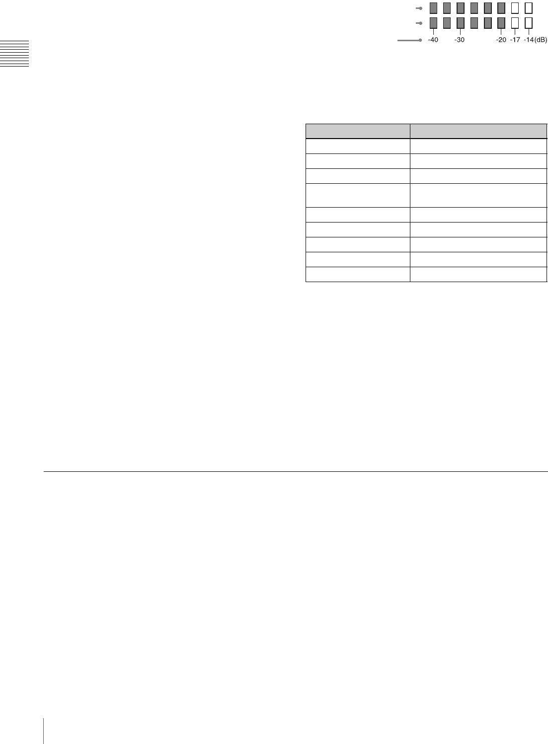
o Audio level
Indicates the level of audio channel 1 and channel 2. The
peak indication of the VDR level meter is related as
follows to the audio level when an 1 kHz sine wave is
input.
p Remaining disc capacity
Indicates the remaining recording time (in minutes) of the
disc.
Examples of remaining recording time indication
q Iris setting/auto iris override
Indicates the F value (iris setting) of the lens.
Also, the auto iris override is displayed using two squares
which appear in the upper and lower parts respectively.
For details, see “Adjusting the Iris” on page 64.
r Setting change and adjustment progress message
display area
For details, see “Change Confirmation/Adjustment
Progress Messages” on page 137.
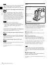
RM-F300 Infrared Remote Commander
To use the infrared remote commander, it is necessary to
assign the remote commander enabling/disabling function
to an ASSIGN switch, and then press the ASSIGN switch
to enable the remote commander. (This function is factory
preset to the ASSIGN 2 switch.)
For details of how to assign a particular function to an
ASSIGN switch , see page 142.
Indication Remaining recording time
90 < More than 90 minutes
90 - 85 90 to 85 minutes
85 - 80 85 to 80 minutes
.
.
.
.
.
.
20 - 15 20 to 15 minutes
15 - 10 15 to 10 minutes
10 - 5 10 to 5 minutes
5 - 0 5 to 0 minutes
No display 0 minute
A
udio channel 1 level indicator
A
udio channel 2 level indicator
VDR level meter indicator


