


1-4
Cisco Video Surveillance 4300 and 4500 High-Definition IP Cameras User Guide
OL-19609-04
Chapter 1 Overview
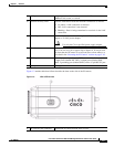
IP Camera Physical Details
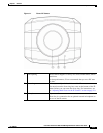
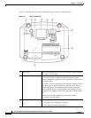
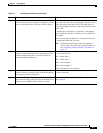
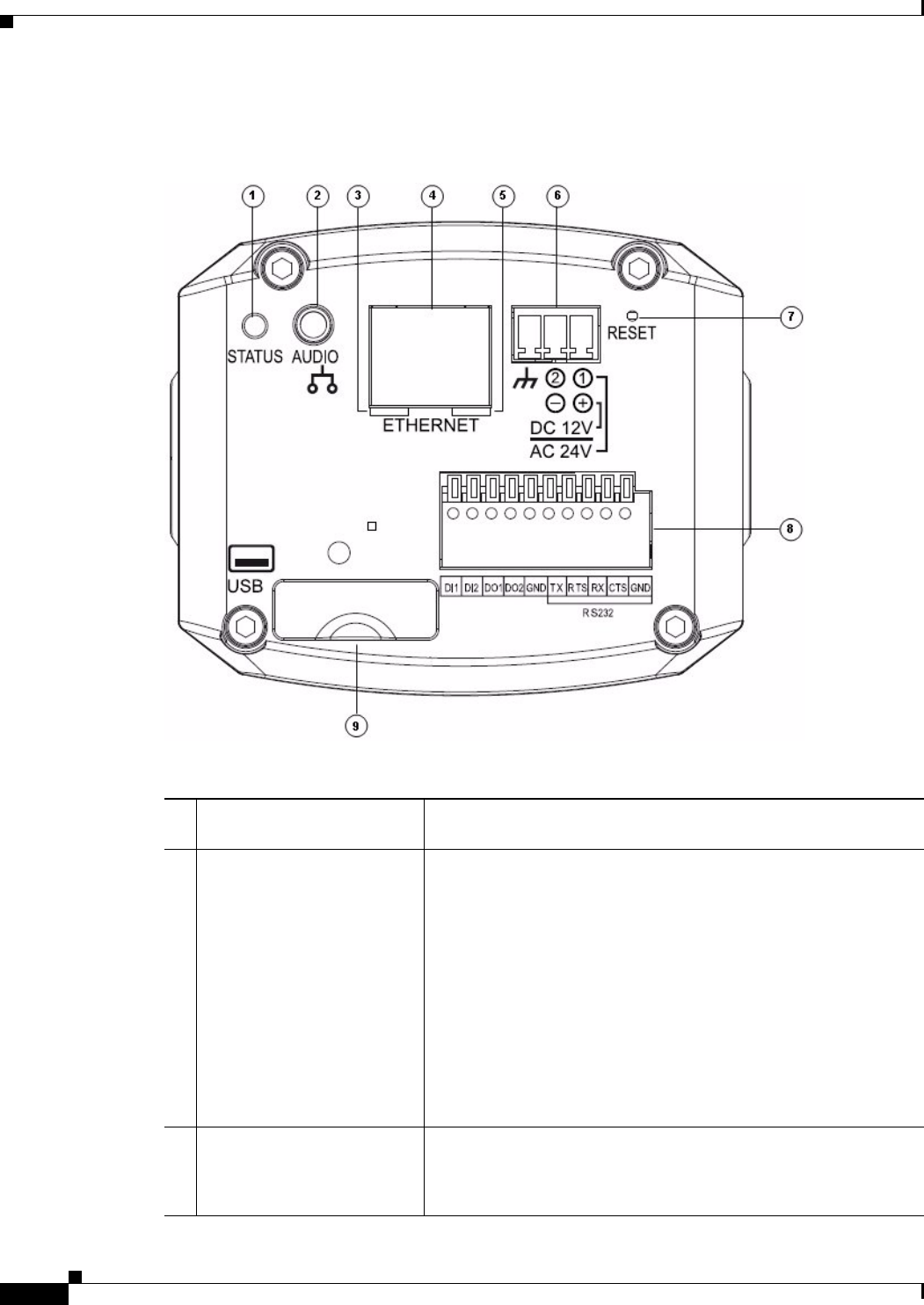
Figure 1-2 and the table that follows describe the items on the rear of the IP camera.
Figure 1-2 Rear of IP Camera
1 Power LED Lights bright when the IP camera is powering up. Lights dim when
the camera is IP operating
2 Audio Port Allows the connection of the audio Y cable that is provided with
the IP camera. You can connect an optional external speaker,
optional external microphone (with pre-amplifier), or both devices
through this cable.
Each device connects to the audio cable through a standard 3.5 mm
mini phone jack. A speaker connects to the green jack, which is
labeled “Audio Out.” A microphone connects to the pink jack,
which is labeled “Audio In.” Microphones and speakers that are
designed for use with PCs usually are compatible with this input
jack.
Connecting an external microphone disables the internal
microphone on the IP camera.
3 PoE LED Indicates information about PoE as follows:
• Lit green—PoE connection is detected
• Off—PoE connection is not detected