


iDP3221 User’s Manual
29
CITIZEN
7. SERIAL INTERFACE
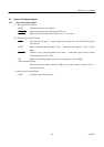
7.1 Specifications
(1) Synchronous system : Asynchronous
(2) Baud rate : 150, 300, 600, 1,200, 2,400, 4,800, 9,600, 19,200 bps
(Selected by the user)
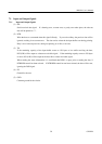
(3) 1-word configuration
Start bit : 1 bit
Data bits : 8 bits or 7 bits (Selected by the user)
Parity bit : Odd, even, or no parity (Selected by the user)
Stop bit : 1 bit or more
(4) Signal polarity
RS-232C
• Mark = Logic "1" (-3 ∼ -12 V)
• Space = Logic "0" (+3 ∼ +12 V)
(5) Received data (RD signal)
•Mark = 1
• Space = 0
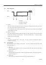
(6) Reception control (DTR signal)
• Mark : Data not transferable
• Space : Data transferable
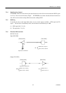
(7) Transmission control (TD signal)
• DC1 code(11H) X-ON : Data receivable
• DC3 code(13H) X-OFF : Data not receivable
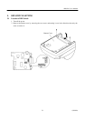
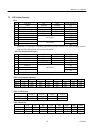
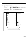
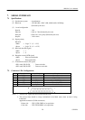
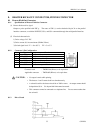
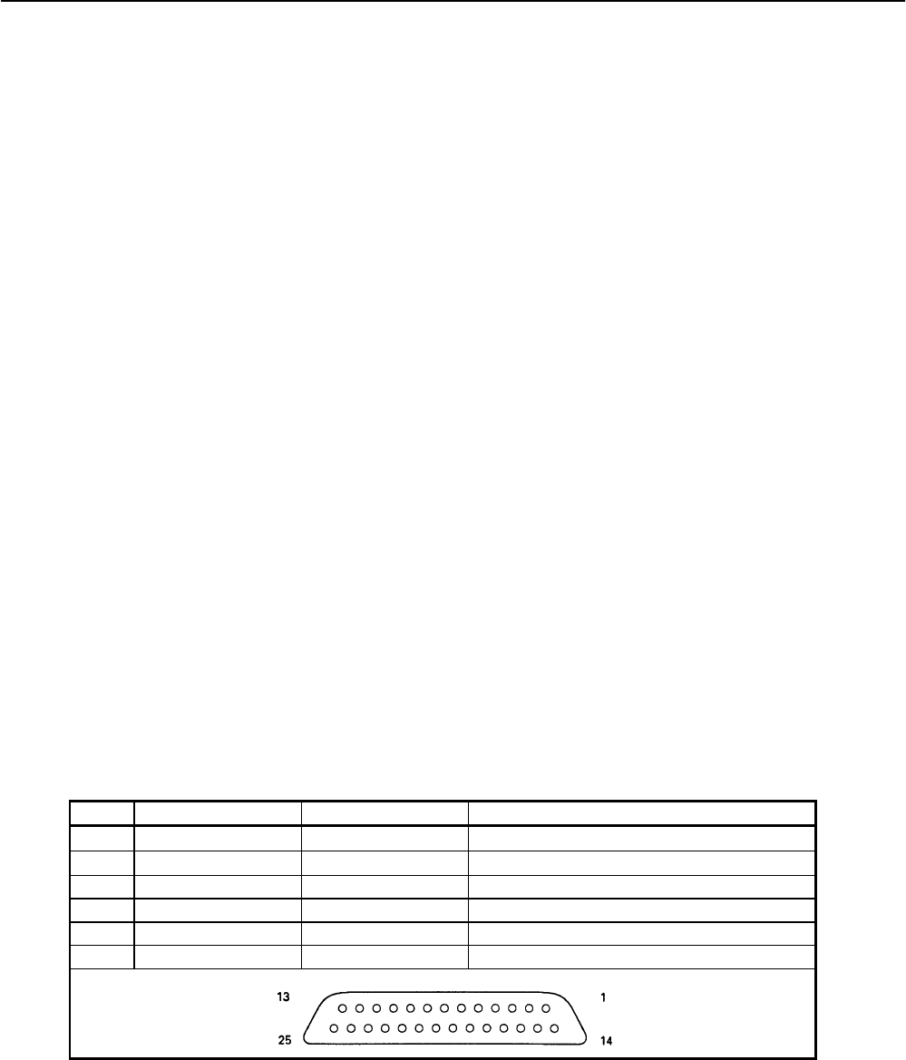
7.2 Connector's Pin Configuration
No. Signal Name Input/Output Function
1FG
Frame Ground
7 GND
Signal Ground
3 RD Input Received Data
20 DTR Output Printer BUSY Signal
2 TD Output Transmitted Data
6 DSR Input Data Set Ready
Notes: 1. The RS-232C signals are based on the EIA RS-232C.
2. The received data should be always maintained in the Mark status when no data is being
transferred.
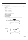
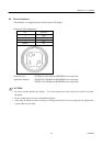
Applicable connectors (D-Sub connectors)
Printer side : 17LE-13250 (DDK) or its equivalent
Cable side : 17JE-23250 (DDK) or its equivalent