


iDP3221 User’s Manual
78
CITIZEN
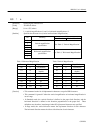
ESC p m n1 n2
[Function] Generating the specified pulses
[Code] <1B>H<70>H<m><n1><n2>
[Range] m = 0, 1
0<n1≤ n2 ≤ 255
[Outline] The signals specified by "n1" and "n2" are output to the connector pin specified by "m".
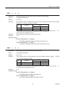
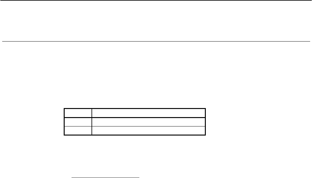
• "m" has the followings.
m Connector Pin
0 Drawer kick pin No.2
1 Drawer kick pin No.5
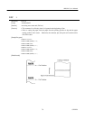
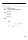
• The ON time is n1×2ms,andOFFtimen2×2ms.
[Caution] • When "m" is beyond a definition range, no signal is output, discarding "n1" and "n2."
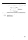
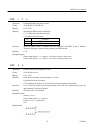
• A drawer drive duty is as follows.
ON time
ON time + OFF time
(The OFF time should be 4 times or more larger than the ON time.)
[Default] The initial value for "m", "n1" and "n2" is not defined.
[Sample Program]
LPRINT CHR$ (&H1B) + "p"
LPRINT CHR$ (0) ; ••••••• Selects pin No. 2.
LPRINT CHR$ (5) ; ••••••• Sets ON time to 10ms
LPRINT CHR$ (50) ; ••••••• Sets OFF time to 100ms
END
≤ 0.2