3
Rear Panel
Rear Panel
2
3
4
1
5
6
7
8
9
10
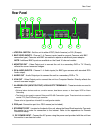
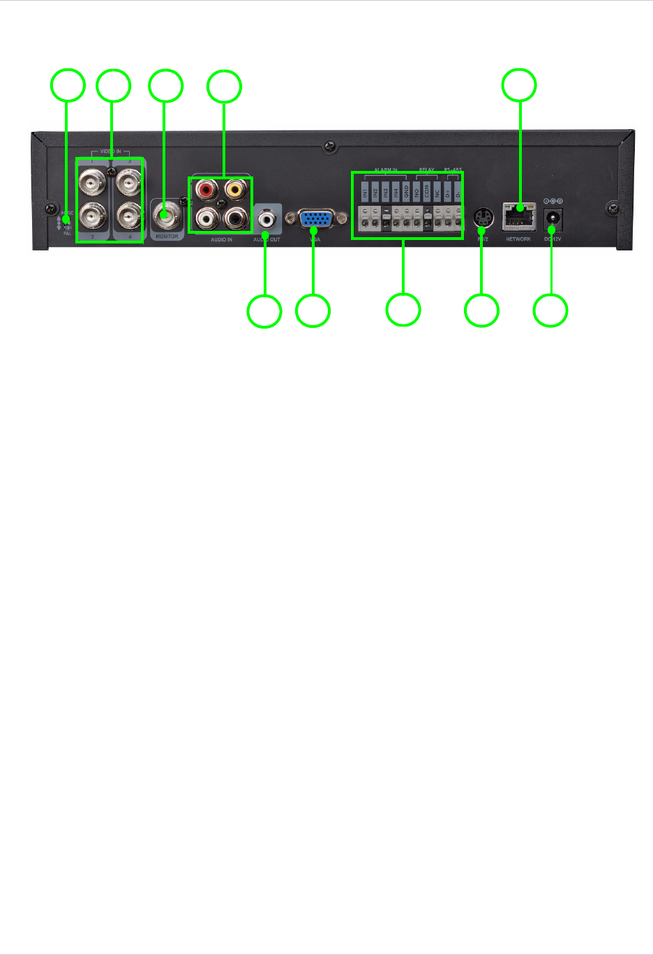
1. NTSC/PAL SWITCH - Set the unit to either NTSC (North America) or PAL (Europe).
2. BNC VIDEO INPUTS - Channel 1~4 Camera inputs (used to connect Cameras with BNC
connection type). Cameras with BNC connections require an additional power adaptor.
NOTE: Additional BNC Inputs are available on the 8 and 16 channel models.
3. MONITOR OUT - Video Output port to connect the unit to a secondary DVR or TV. Directly
reflects the current onscreen images.
4. RCA AUDIO INPUTS - Channel 1~4 Audio inputs (for BNC type cameras with standard RCA
Audio output).
5. AUDIO OUT - Audio Output port to connect the unit to a secondary DVR or TV.
6. VGA OUT - Video Output port to connect the unit to a Computer Monitor. Directly reflects the
current onscreen images.
7. ALARM BLOCK (INPUT/OUTPUT) & RS-485 PTZ TERMINALS - These terminals are used to
connect:
• External alarm devices such as a motion sensor, door/alarm sensor, or time lapse VCR for Alarm
Recording.
• The block is also used to connect Relay and RS-485 Connection types. These terminals are used to
control PTZ (Pan/Tilt/Zoom) type cameras.
Please refer to Appendices #4 and #5 for configuration details.
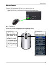
8. PS/2 port: Connection port for a PS/2 mouse (not included).
9. ETHERNET PORT - Located on the back of the unit, above the Alarm Block terminals. Connects
the monitor to a router for connection to the internet. Refer to the appendices for Remote
Connection setup.
10. DC POWER INPUT - Connect the AC power using the power cord provided with the unit from
the monitor to an electrical outlet


