3
General Information
20
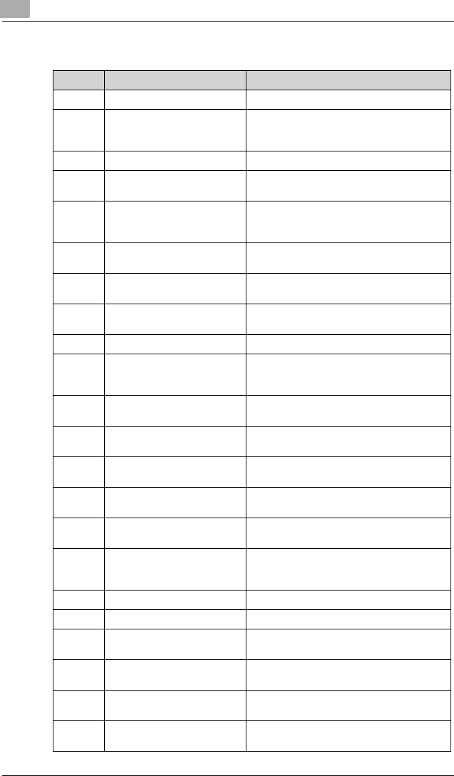
3.7 Electrical Parts Function
Symbol Name Function
CNT1 Total Counter Counts the number of prints.
F1 Fuse Power Fuse
100/120V Area: 250V, 10A
220-240V Area: 250V, 6.3A
L1 Filter Coil Power-supply noise filter
LA1 Projection Lamp The source of the light for projecting the film
image
M1 Scan Motor The motor which rotate the 1st scanning
mirror when carrying out scan of the film
image to CCD.
M2 Scan Table Motor The motor for moving a scanning table to a
reader position and a scanning position.
M3 Power Unit Cooling Fan Motor Exhausts the heated air surrounding the
Power Unit out of the machine.
M4 Projection Lamp Cooling Fan
Motor
Exhausts the heated air surrounding the
Projection Lamp out of the machine.
M5 Auto Image Rotation Motor The motor which rotate a prism.
PC1 Image Leading-Edge Position
Sensor
Detects the slit on the Scan Mirror mounting
plate.
Leading-edge detect :L
PC2 Scan Mirror Position Sensor Detects the home position of the Scan Mirror.
Scan Mirror home position detect :L
PC3 Reader Position Sensor Detects the reader position of the Scan Table.
Reader position detect :L
PC4 Scan Position Sensor Detects the scan position of the Scan Table.
Scan position detect :L
PU1 Main Power Unit Converts the power voltage from AC voltage
into DC voltage.
PU2 Projection Lamp Regulator Converts the power voltage from AC voltage
into DC voltage and supplies that to LA1.
PU3 Option Power Unit
(for RFC-21)
Converts the power voltage from AC voltage
into DC voltage (DC-24V) and supplies that to
optional RFC21.
PWB-A CCD Board The CCD reads the film image.
PWB-BB Main Control Board Controls all machine operation.
PWB-C Control Panel Board The keys and LEDs which make operation of
the machine possible are included.
PWB-D Option I/F Board The Interface board which connects an option
(RFC, MARS).
PWB-EE Printer I/F Board Communicates with the Main Control Board
and printer.
PWB-F Option I/F Board Communicates with the Main Control Board
and option (MARS, RFC).


