


Mechanical and Electrical
4
47
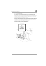
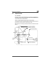
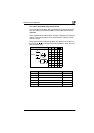
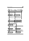
4.3.6 Mirror Scan Motor (M1) Control Circuit
Drive of the Scanning Motor (M1) is controlled by the signals which are
input to the Motor Driver Board (PWB-T) from the Main Control Board
(PWB-BB).
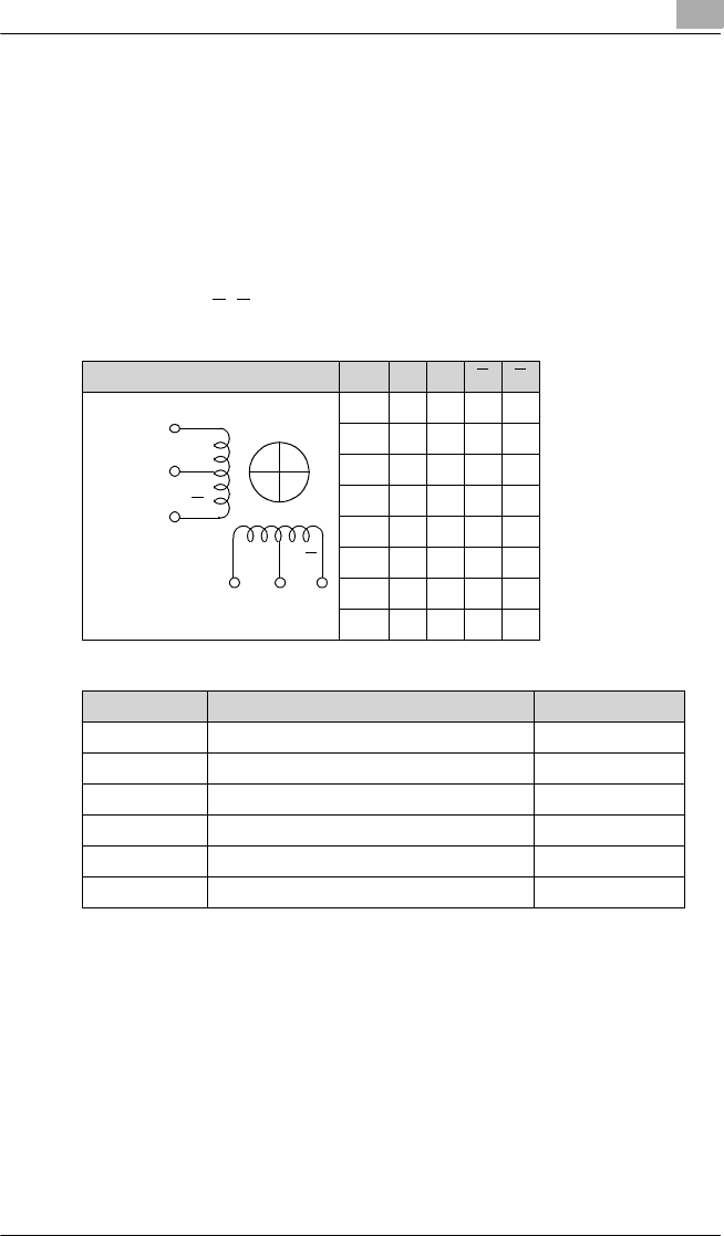
These signals determine the direction (forward or backward) and speed of
rotation of the Scanning Motor when the Scan Mirror makes a prescan
and scan motion.
These signals cause the Scanning Motor drive pulses to be output from
the pins (A, B, A
, B) of the Motor Driver Board (PWB-T), which turns the
Scanning Motor (M1).
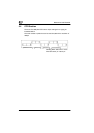
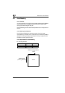
Motor Step A B A B
1 LHHH
2 LLHH
3HLHH
4 HLLH
5 HHLH
6 HHLL
7 HHHL
8 LHHL
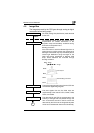
Motor Step Speed (Full Size)
Scan(800dpi) 1
→
2
→
3
→
4
→→
5
→
6
→
7
→
8
→
1
→
..... 82.5mm/sec.
Scan(600dpi) 1
→
2
→
3
→
4
→→
5
→
6
→
7
→
8
→
1
→
..... 110mm/sec.
Scan(400dpi) 1
→
2
→
3
→
4
→→
5
→
6
→
7
→
8
→
1
→
..... 165 mm/sec.
Scan(300dpi) 1
→
2
→
3
→
4
→→
5
→
6
→
7
→
8
→
1
→
..... 220 mm/sec.
Scan(200dpi) 2
→
4
→
6
→
8
→
2
→
..... 330 mm/sec.
Prescan 8
→
6
→
4
→
2
→
8
→
..... 330 mm/sec.
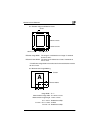
A
A
B
B
DC24V
DC24V
N
SN
S