


Contents
ii
Contents
1 Safety Precautions for Inspection and Service
1.1 WARNING.............................................................................................. 1
1.2 CAUTION............................................................................................... 4
1.3 Other Precautions................................................................................ 6
1.4 Used Batteries Precautions ................................................................ 7
2 Installation
2.1 Installation Environment ..................................................................... 8
2.2 Usage Environment ............................................................................. 8
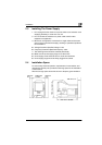
2.3 Installing The Power Supply ............................................................... 9
2.4 Installation Space................................................................................. 9
3 General Information
3.1 Specifications..................................................................................... 10
3.1.1 MS 6000........................................................................................ 10
3.1.2 MS 6000 & MSP3000 Printer System ........................................... 12
3.1.3 MS 6000 & MSP2000 Printer System ........................................... 12
3.2 System Configuration........................................................................ 13
3.3 Connection Mode............................................................................... 14
3.3.1 PR Mode (Scanner + Printer)........................................................ 14
3.3.2 PC Mode (Scanner + Personal Computer).................................... 14
3.4 Parts Identification............................................................................. 15
3.5 Component Layout ............................................................................ 16
3.6 Electrical Components Layout ......................................................... 17
3.7 Electrical Parts Function................................................................... 20
3.8 Connectors Layout ............................................................................ 22
3.9 Electrical Service Parts on P.W.Boards........................................... 24
3.9.1 Main Control Board (PWB-BB)...................................................... 24
3.9.2 I/F Board (PWB-EE) ...................................................................... 24
3.9.3 I/F Board (PWB-SS) ...................................................................... 25
3.9.4 Main Power Unit (PU1).................................................................. 25
3.9.5 Projection Lamp Regulator (PU2) ................................................. 25
3.9.6 Optional Power Unit (PU3) ............................................................ 25