


PG-FP5 V2.13 PROGRAMMING GUI USAGE
R20UT2924EJ0200 Rev.2.00 Page 13 of 71
Mar 02, 2015
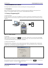
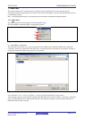
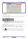
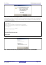
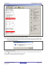
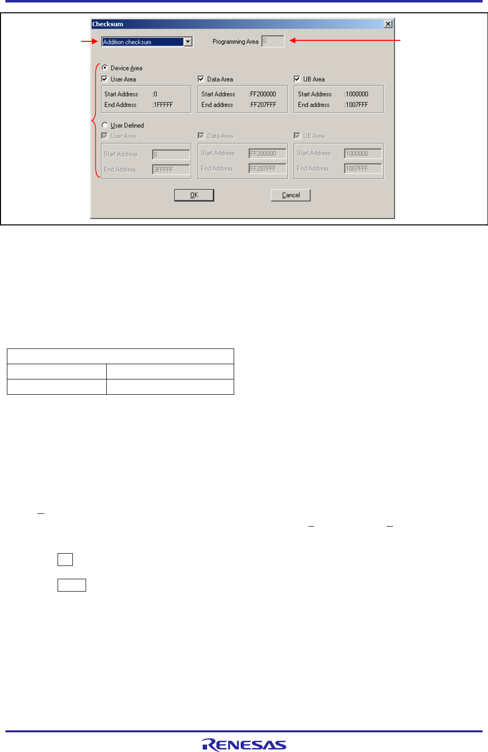
Figure 1.10 Checksum Dialog Box
<1> Programming area
The valid programming area is displayed.
<2> Checksum calculation mode selection
Select the mode for calculating checksum of the selected program file. Selected calculation modes differ with the MCU.
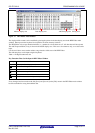
Table 1.2 Checksum calculation
Checksum calculation
Addition checksum
32-bit arithmetic (addition)
CRC sum (32bit)
32-bit CRC
Note With the 32-bit arithmetic (addition) mode, the lower 8 digits of the result to which a value is added from 00h in 1-
byte units are displayed.
With 32-bit mode, the 8-digit result of CRC32 function calculation is displayed. For details on arithmetic
specifications, refer to Common APPENDIX B SUPPLEMENTARY INFORMATION Figure B.2 32-bit CRC
Calculation Specifications.
<3> Address range selection
Select the range for calculating checksum of the selected program file. If there is no program file data in the specified
range, the specified range is filled with FFh for calculation.
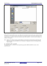
Device Area: From the start to end addresses of the device, which are contained in the selected PR5 file
User Defined: Any range can be specified by inputting the addresses to the [Start Address] and [End Address] text
boxes.
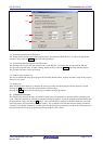
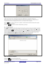
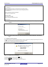
Clicking the OK button displays the calculation result in the [File Checksum] area in the action log window and
programmer parameter window.
Clicking the Cancel button closes the dialog box without saving the settings made in the Checksum dialog box.
Note When the valid programming area is changed or a program file is downloaded, the checksum result will be
cleared.
<1>
<2>
<3>